

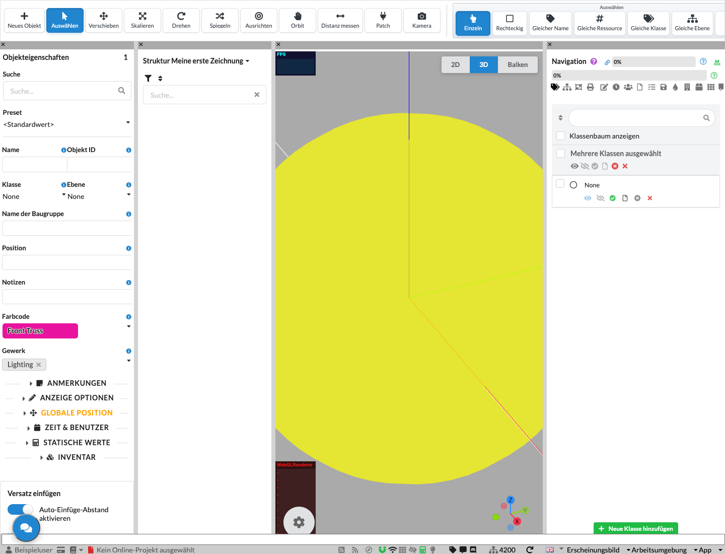
The Production Assist desktop app is divided into eight work areas. The available commands and tabs depend on the work environment and the active drawing. This page explains what each area is used for. The linked chapters describe fields, submenus, and dialogs.
| No. | Area | What it is used for |
|---|---|---|
| 1 | Menu Bar | Open commands, settings, and additional windows |
| 2 | Toolbar | Use tools to select, insert, and edit objects |
| 3 | Object Properties | View and edit the properties of the selection |
| 4 | Paste Offset | Set offsets for duplicates and run copy commands |
| 5 | Scene Tree | Manage objects and their Assembly Groups in the drawing |
| 6 | Renderer | View and edit the drawing in 2D, 3D, Beam, or Bridle view; Bridle Builder and Truss Builder open their own creation workspaces |
| 7 | Navigation | Manage Classes, Layers, Presets, Assembly Sheets, and other tabs |
| 8 | Information Line and Command Line | Check status and connection, and enter text commands |
If you have closed or hidden all docked tabs, Refresh User Interface appears in the empty area. Click Reset UI to restore the default layout for the respective view. The windows reappear and the layout is saved.
This help is available in the desktop app, browser editor, Vectorworks web palette, and tablet layout of the iOS app. In the Vectorworks web palette and browser editor, it also appears in worksheet view when its docked tabs are closed. The help is not displayed as long as a tab remains open, such as Paste Offset. The iPhone view uses fixed tabs instead of a freely arrangeable window layout.
Use the Menu Bar to open drawings, import data, start calculations, and access settings or help, for example. The visible menus vary by platform and integration.
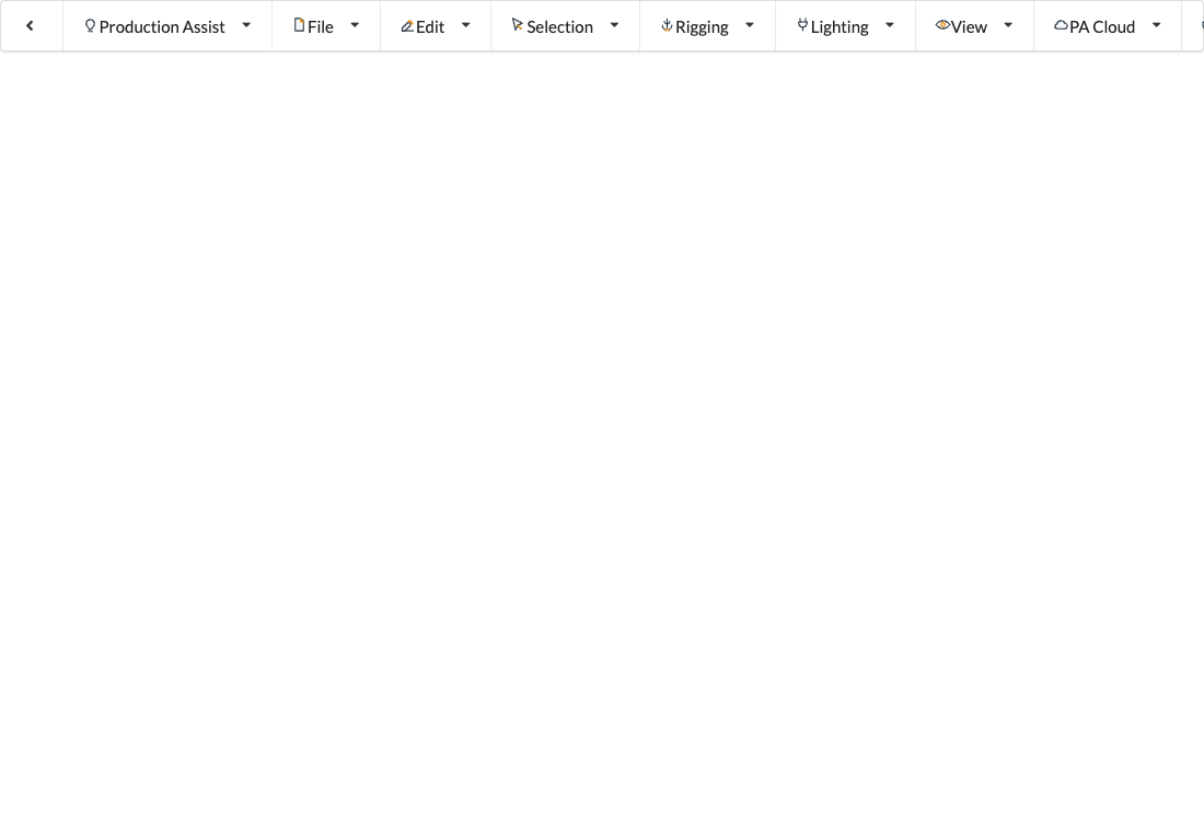
The Menu Bar chapter describes all commands, submenus, and related dialogs. The Development menu in the example screenshot appears only in Development builds; macOS also has the Production Assist app menu.
Choose a tool in the Toolbar. The available options change with the tool and work area. For example, New Object lets you select Symbol, GDTF, or Mesh resources to insert.

The Toolbar chapter explains the tools, insertion modes, and resource selection.
Edit the properties of selected objects in Object Properties. The available groups depend on the object type and, for a multiple selection, on the properties the objects have in common. Expand a group to see its fields.
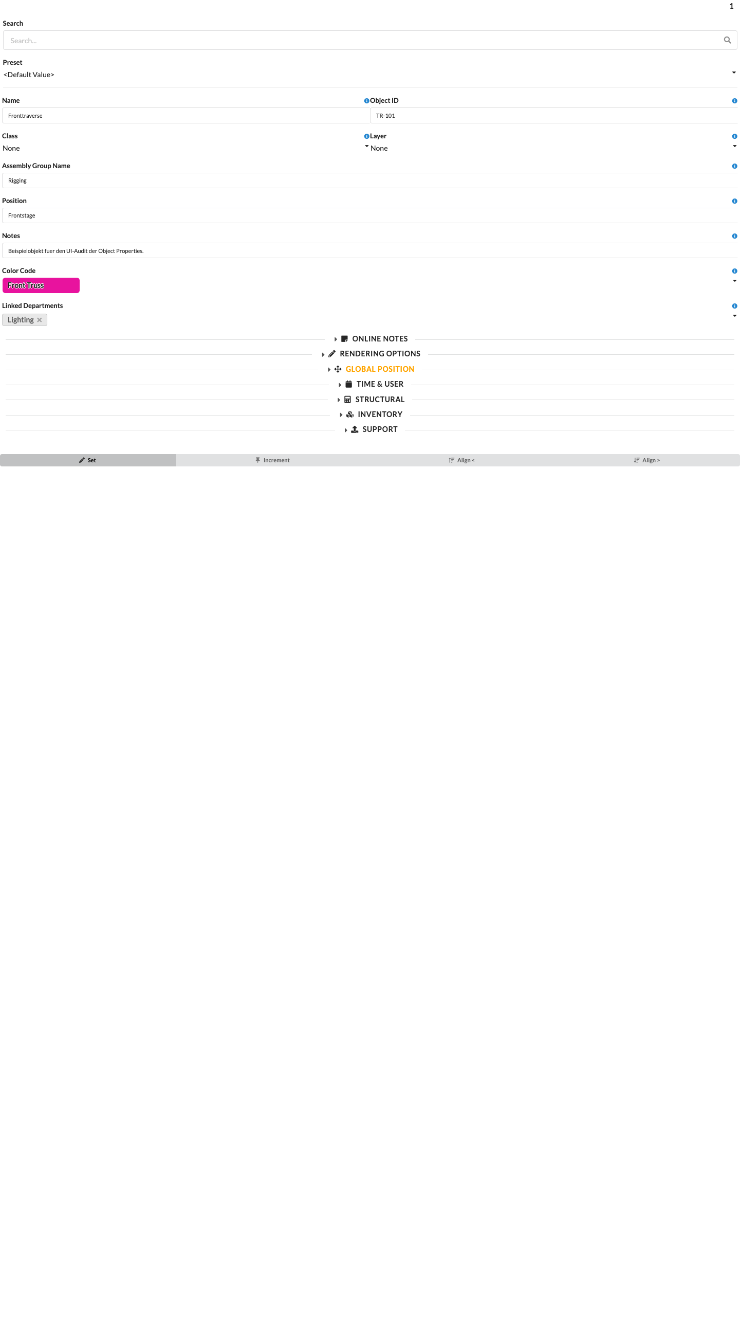
See Object Information for expanded groups, field tables, and object-specific dialogs.
The standalone Paste Offset window sets the offset for duplicate commands on the X, Y, and Z axes. Open it using Window → Paste Offset. In desktop and tablet layouts, you can move, split, and resize the window like other areas. On iPhone, it appears as its own tab. Enter the desired distance on each axis, then use the plus or minus button to duplicate the selected objects in that direction. Flip 180deg and Move X+ duplicates the selection, rotates the copies by 180°, and moves them in the positive X direction. The commands are also available under Edit → Duplicate. Keyboard shortcuts depend on the active CAD integration and the shortcuts configured there.
For the native copy and move commands in AutoCAD and BricsCAD, if no selection has been made, the command first prompts you to select blocks. You can then confirm the existing paste offset with Enter or enter a new distance directly in the CAD command line. A new entry updates the paste offset for the selected axis in Production Assist. Enter the distance in drawing units; Production Assist converts it to millimeters. The native commands follow the axes of the current user coordinate system (UCS). PACX/PACY/PACZ and PAMX/PAMY/PAMZ use the distance with its sign; PACX-/PACY-/PACZ- and PAMX-/PAMY-/PAMZ- reverse the sign. Positive and negative nonzero distances are possible. The entered sign is stored unchanged in the paste offset. The command remains active after each action: press Enter once each time to repeat the action with the last confirmed distance. Esc ends the command; completed actions and confirmed distances are retained.
Enable Auto Paste Offset automatically adjusts the paste offsets to the X, Y, and Z extents of the selected structural geometry. This is useful when you want to arrange copies directly next to one another. The manually entered axis offsets remain available when automatic adjustment is switched off. The same option is available under File → Settings... → Renderer.
| Panel/Field | Detailed Description |
|---|---|
| Paste Offset X | Sets the distance for duplicates in the X direction. The X Plus and X Minus buttons duplicate the selection using this distance. |
| Paste Offset Y | Sets the distance for duplicates in the Y direction. The Y Plus and Y Minus buttons duplicate the selection using this distance. |
| Paste Offset Z | Sets the distance for duplicates in the Z direction. The Z Plus and Z Minus buttons duplicate the selection using this distance. |
| Enable Auto Paste Offset | Automatically adjusts the paste offsets to the X, Y, and Z extents of the selected structural geometry. The option is also available under File → Settings... → Renderer. |
| Flip 180deg and Move X+ | Duplicates the selection, rotates the copies by 180°, and moves them by the positive X paste offset. |
The Scene Tree displays the objects in the active drawing as a hierarchy. Use it to select and search for objects, organize them into Assembly Groups, and switch between open drawings when available.
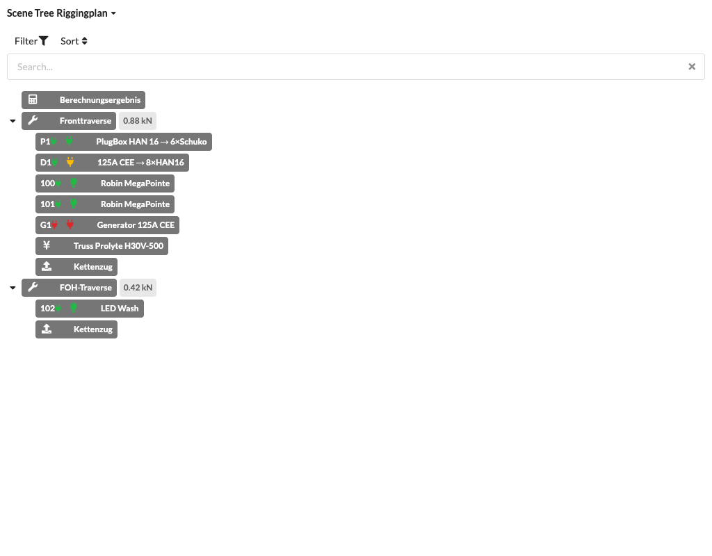
The Scene Tree chapter explains filtering, sorting, selection, and Assembly Groups.
View and edit the drawing in the Renderer. The desktop app provides 2D, 3D, Beam, and Bridles views; the visible objects also depend on the settings in Navigation.
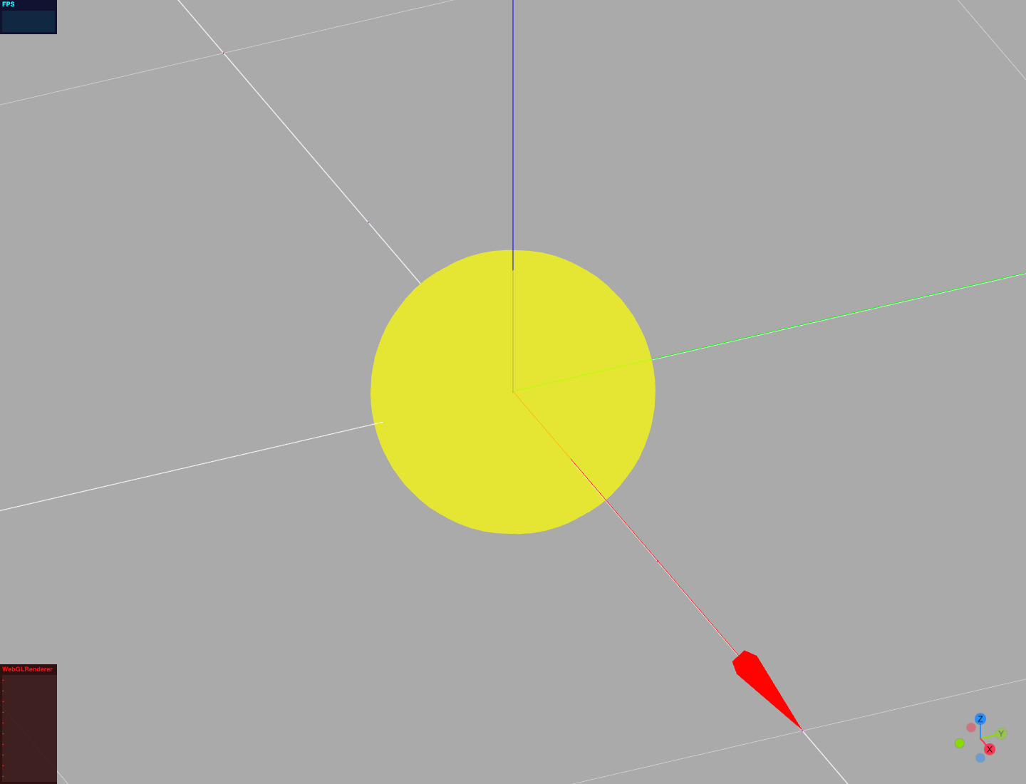
Renderer describes changing views, the camera, and drawing controls. Truss Builder and Bridle Builder open a dedicated creation view in the desktop app. You can access them from the Creation workspace menu in the footer or from the buttons at the top right of the Renderer. In the iOS app, open the builders using the mode selector in the graphics area. While a builder is open, the general Toolbar, Scene Tree, Navigation, Object Properties, and footer are hidden. Full editor returns to the previous editor layout and Renderer view. Truss Builder creates structural truss runs, point loads, and hoists. There you can edit the run, loads, hoist position, capacity, and roof connection. The calculation view for individual structural beams is described in Beam View.
In Bridles, the settings for the selected bridle appear above the drawings. The fields adapt to the available width; the header collapses or expands the settings. Dimensions, the parts library, and basket or strand parts open in separate expandable areas. Bridle Builder also provides its own creation and coordinate fields for two- and three-leg systems. See Bridle View and Bridle Builder for instructions.
Use the tabs in Navigation to manage the structure and planning of the drawing, for example Classes, Layers, Presets, users, Assembly Sheets, transport containers, and load combinations. Visibility and calculation settings affect how objects are displayed or evaluated.
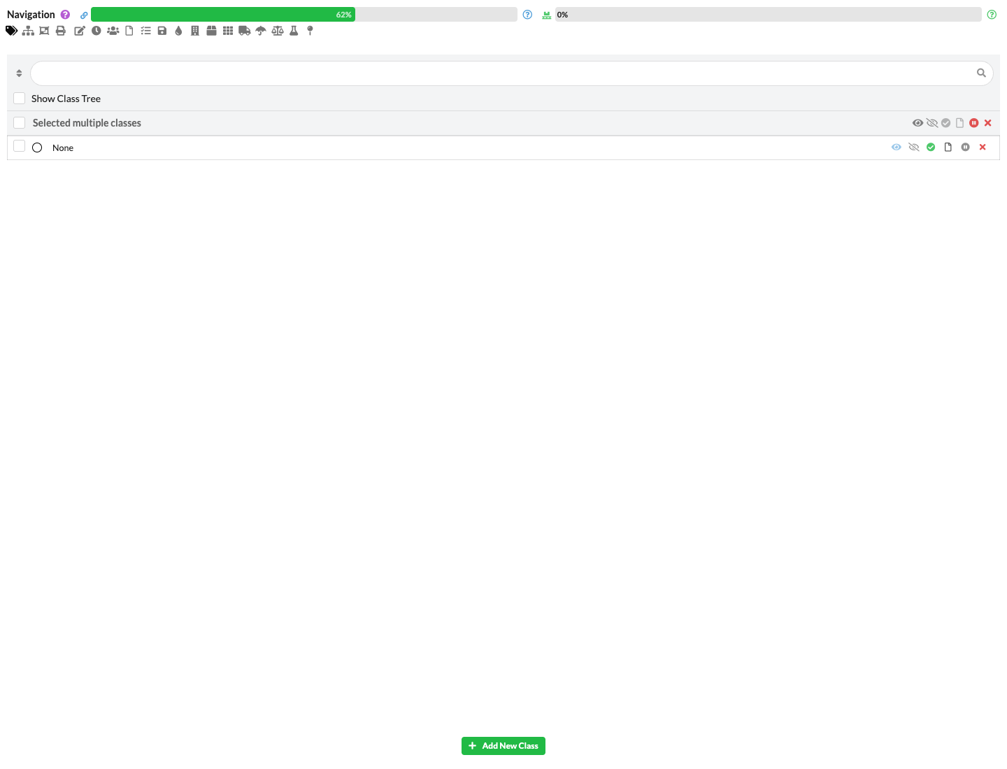
Navigation explains all tabs, their tables, controls, and editing dialogs. For tasks and Assembly Sheets, also see Work Planning.
The Information Line at the bottom displays user, project, and connection status, and provides controls for language, calculation, and display. In the desktop footer, Creation workspace opens Truss Builder or Bridle Builder. The footer is hidden while a creation view is open. The Command Line directly above it accepts text commands for selection and changes. The Command Line is not visible in the mobile layout or the iOS app.
The Command Line lets you run commands quickly by entering text. All available commands are listed in the Command Line chapter.
On the left, the Information Line displays your username and the name of the drawing you are working in on the Production Assist online platform. If you are working with an offline drawing, it displays “no online project selected”.
On the right side of the Information Line, you can quickly change the program language using the “flag” icon. You can also use the “calculator” to turn automatic calculation on or off, and the “tag” icon next to it to turn error messages for building a structural system on or off.
You can also send feedback by double-clicking the “speech bubble”. A feedback window opens where you can send feature requests or support requests. You can also send crash reports through this window. All content you send us is registered in our system, entered, and processed.
Next to the speech bubble is a Network Indicator icon, which displays Production Assist network connections. The server icon in the desktop app and supported plugin interfaces opens the MCP server connection details. The same connection details and copyable STDIO values are available in the settings window under MCP. There you can find the port, a local connection address, and IPv4 addresses that other devices can use to reach the server. Use the appropriate HTTP address in the MCP client; all addresses end in /mcp. Use the copy icon next to an address to copy it to the clipboard.
The Local STDIO Targets list shows registered targets from the desktop app and CAD plugins, including the host application, channel, version, installation ID, and status. Select a ready target. For an MCP client that offers separate fields for a local STDIO connection, select STDIO as the type in the custom MCP connection dialog and transfer the values from Manual STDIO Configuration to the corresponding fields:
--mcp-bridge, --target, and the instance ID of the selected target.For Codex, click Copy Codex Configuration to copy the complete Codex configuration entry for the selected target. The local connection address remains available for MCP clients that use HTTP. Select Available MCP commands to open a searchable list of all MCP commands. Select a command to view its description, input parameters, and documented output parameters. The complete JSON schema is also available.
Expand Server instructions in the same list to read the shared usage guidance. It explains the active drawing, object identifiers (UUIDs), properties, selection, units, and how to poll running jobs. The English text matches the instructions sent to an MCP client when it connects. It remains visible even when the command search has no matches.
The public MCP tools also support bridle material sets and individual bridle assignments. An AI assistant can read available parts, selectively enable or disable them, and add or change components. Changes to a material set update all bridles that use that set. See Change Bridle Parts Using an AI Assistant for the procedure and how it differs from editing an individual bridle.
A connected AI assistant can also draft and revise calculation reports. The available functions include the report context with shared writing instructions, reading and saving the draft, and preview and PDF export. Clients with selectable MCP prompt templates display structural_report. See Create a Calculation Report with an External AI Assistant for the procedure, the project data that is transferred, and the required review.
With multiple applications open, each can use its own MCP port. If the configured port is already in use, the application uses another available port. Therefore, copy the connection address from the specific application whose drawing you want to edit. The command list also includes retrieving, downloading, and importing online resources from the Resource Selection dialog; the server instructions explain the process through inserting a symbol.
For an overview and parts editing for all bridles, see Bridle View.
For more detailed information about this area, see PA NET and Command Line.
For an overview and parts editing for all bridles, see Bridle View.