

In the Toolbar, choose tools for inserting, selecting, and editing drawing objects. The available tools depend on the work environment and the tools enabled there. When you select a tool, the Toolbar displays its settings and modes.
The main tools include New Object, Select, Move, Scale, Rotate, Mirror, Align, Orbit, Measure Distance, and Patch. The desktop app also has Camera for scanning QR codes. Available tools and settings may vary by platform and workspace.
Select is active when you start. The following sections describe the main tools and how to use them.

After you select the New Object tool, the Toolbar displays different object types and insertion modes. The table lists commonly used object types.

| Tool | Purpose |
|---|---|
| Symbol | Inserts an object from a symbol definition, such as a truss or power distributor. |
| GDTF | Inserts a fixture type whose device data is described in the General Device Type Format. |
| Mesh | Inserts 3D geometry. Depending on the resource, a mesh can contain additional Production Assist properties. |
| Connection | Creates connections such as ropes, pipes, drops, bridles, or Truss Crosses. The available tools depend on the selected connection type. |
| Dimensions | Inserts a dimension between two points in the Renderer. |
| Assembly Group | Creates an empty Assembly Group to which you can then assign objects. |
Other object types, such as text, cable paths, curtains, polygons, loads, or print labels, may also be available depending on the workspace.
The resource selector provides the following sources for GDTFs, meshes, and symbols:
Current Drawing shows resources available in the active drawing, including fixture types imported from GDTF.
Local Resources shows resources stored on this computer and available offline. Select Open Local Resources Folder in the resource dialog to open the actual location on your system. You can place your own .lrwx resource files there.
Online Drawing shows resources from the Production Assist Library. User Resources shows resources for the selected user account. Online resources require an internet connection. For resources that are not yet available locally, you can select Download & Import.
Depending on the source, you can browse resources by categories such as Fixtures, Power, or Truss.
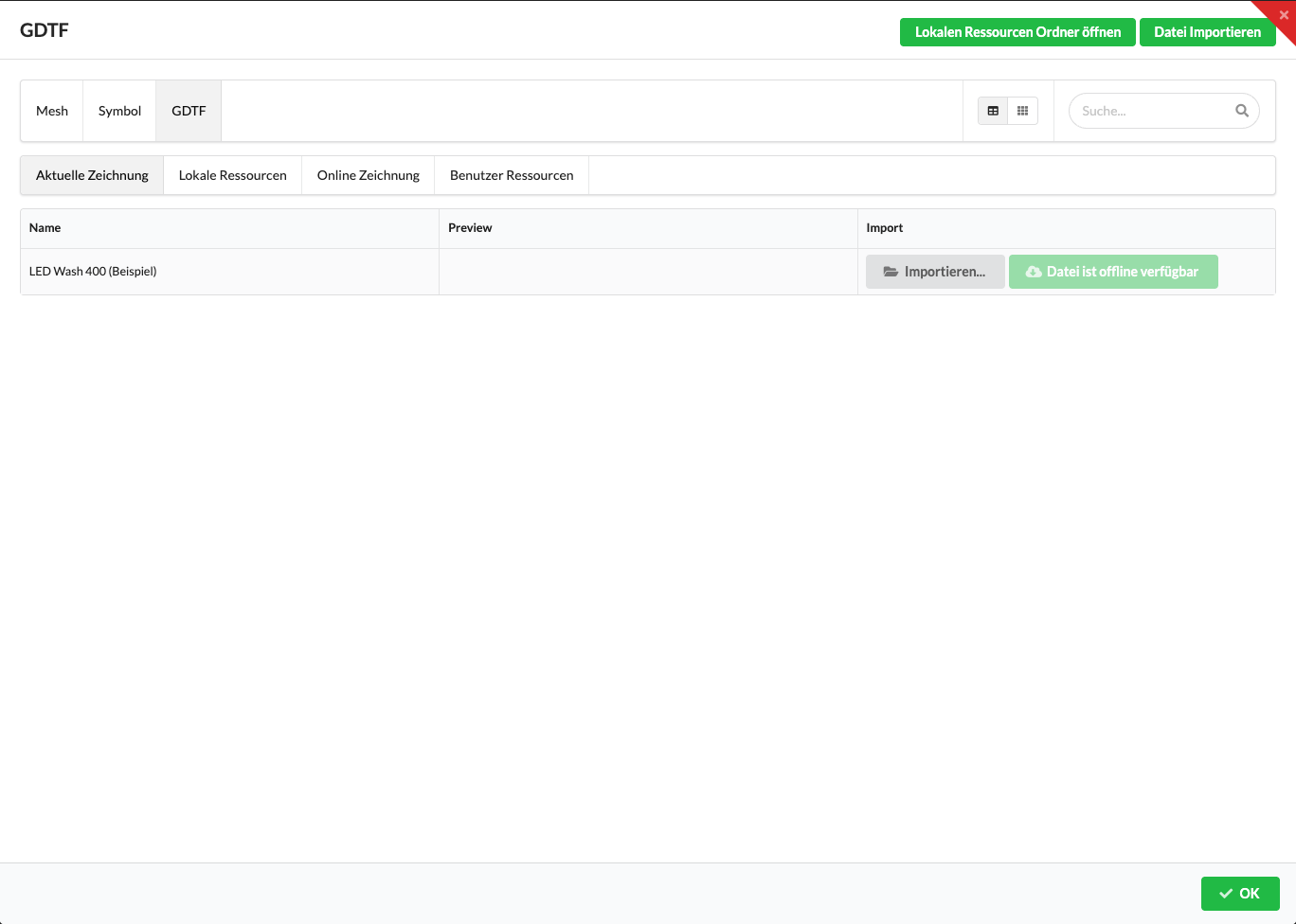
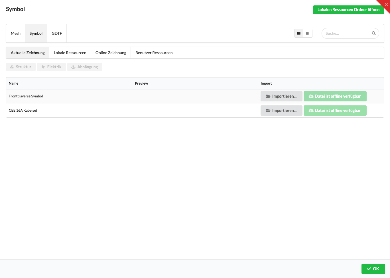
The Assembly Group option creates an empty Assembly Group in the Renderer and the Scene Tree. You can then name it in Object Properties and move objects into it. To group objects that are already selected, select at least two objects and use Group Selected Objects into Assembly Group in the context menu. Enter a name in the Assembly Group Name dialog and confirm with OK. For further steps, see Scene Tree context-menu commands.
To insert an object, select its type in the Toolbar. Find the resource you want in the resource selector. Click its entry or select Import... or Download & Import. The resource then becomes the active insertion tool; place the object in the Renderer. Download only downloads an online resource to the computer; it does not make it the active insertion tool. You can add a new .gdtf or mesh file to the library with Import File; this initially imports only the resource.
| Field | Description |
|---|---|
| Search and categories | Filter the visible resources by name and resource type. The entries shown depend on the current drawing and the selected local or online source. |
| Mesh / Symbol / GDTF | Select the resource type whose entries appear in the list. |
| Current Drawing / Local Resources / Online Drawing / User Resources | Select the source for the list. Online sources require a connection. |
| List and tile view | Change how results are displayed; the selected resource stays the same. |
| Name / Preview | Show the resource name and, when available, a preview. |
| Resource entry | Activates the selected symbol, fixture, or mesh definition for the insertion tool. The object is then placed in the Renderer. |
| Import... / Download & Import | Activates the resource for the insertion tool. Download & Import appears for online resources that are not yet available locally; after it loads, place the object in the Renderer. |
| Download | Downloads an online resource to the computer without activating it for the insertion tool. After the download, it is available offline. |
| File is available offline | Indicates that the resource is already stored locally. |
| Import File | For GDTF and Mesh, opens the file chooser to add a local file to the resource library. This button is not available for symbols. |
| OK | Closes the resource selector. Closing the dialog does not import a resource. You can also use the X in the top-right corner or press Esc. |
The cursor returns to the Renderer and marks the insertion point in yellow. Click to place the object where you want it. Click again to insert more objects with the same properties. On a touchscreen, the insertion point appears offset above your finger so the preview remains visible. Drag your finger to move the preview, then release it at the desired position. A short vibration confirms snapping to an existing truss. The coordinate display appears only when using a mouse.
Depending on the object type, the Toolbar also offers insertion modes besides point insertion: Point Align, Line, and Array. With Point Align, set the orientation using a second point. Line distributes multiple objects along the line you draw; use Measure to set the spacing. Array arranges objects along a drawn line or path. Available insertion modes vary by object type.
The insertion modes appear in the Toolbar next to the active resource type. The available modes depend on the type. When you switch types, the last insertion mode used for that type is restored.



In the Edit Mode of a symbol definition, New Object shows the element types that you can add to the definition. These include Mesh, Magnet, Electrical, Inventory, Structure, Storage, Audio, Origin Reference, Curtain, Polygon, Load, and Dock.

While an insertion tool is active, press X to switch to the Select tool. Press Esc to cancel an insertion that has not been completed. After inserting an object, do not press X if you want to place more instances of the same object.
For trusses, Magnets show the snap points at the ends. Move the cursor to the end of an existing truss. Check the preview and click to insert the new truss there. Press Shift to cycle through the available snap orientations. Press Ctrl (Windows) or Control (macOS) to switch the magnet point of the truss being inserted. Then check its alignment in the 3D view.
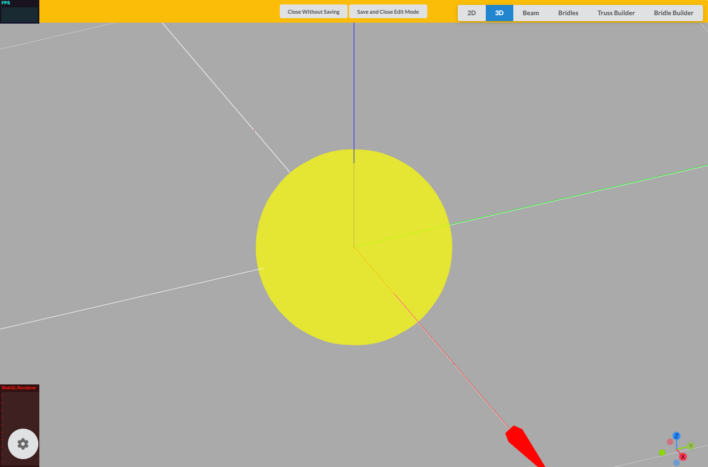
Use this tool to insert dimensions in the Renderer. Click the two points that the dimension should reference in sequence.
Use Connection to create structural connections or align trusses for a connection.
Press Esc to cancel a point sequence that has not been completed.
| Tool | Use | Required clicks |
|---|---|---|
| Rope | Flexible rope connection between two structures | 2 points |
| Truss Cross | Connection between two structural members that cross appropriately in the model | 2 objects |
| Drop | Drop using a selected symbol definition between two structures | 2 objects |
| Pipe | Pipe with a selectable cross section between two points | 2 points |
| StackTrusses | Stack a second truss system on top of the first | 2 objects |
| Bridle 2 Leg | Two-leg bridle | 2 connection points and 1 insertion point |
| Bridle 3 Leg | Three-leg bridle | 1 insertion point and 3 connection points |
| Bridle 4 Leg | Four-leg bridle | 1 insertion point and 4 connection points |
Use Rope to connect two structures with a flexible connection, for example for diagonal bracing.
A rope carries tension only. Use Pipe if the real connection can also carry compression.
Use Truss Cross to connect two detected structural members that cross in plan view and have a suitable height difference in 3D.
The plan view alone is not sufficient. In the 3D or side view, check that there is a suitable height difference between the detected structural axes. The connection types, automatic creation, and result checks are described in Creating and Checking Truss Crosses.
Use Drop to insert a suspension between two structures. The Drop uses a symbol definition with the required support geometry.
For a vertical Drop, the connection points must be vertically aligned in plan view.
Use Pipe to create a structural pipe between two points. For example, use it to model a Corner Brace that can carry both compression and tension.
A Pipe that only appears to touch a structure does not transfer force in the calculation. See Modeling and Checking Corner Braces for a complete example.
StackTrusses aligns two trusses or connected truss systems vertically.
The tool moves the connected system of the second truss. It does not always insert a Truss Cross itself. Whether Truss Crosses are created automatically after alignment depends on the Truss Cross settings and valid geometry.
The click order for Bridle 2 Leg differs from the tools for three- and four-leg bridles.
On the third click, Production Assist projects the insertion point in plan view onto the line segment between the first two points. If you click outside the segment, the projection is limited to the nearest endpoint. The clicked height of the insertion point is retained.
After insertion, check the following:
Use Select System Objects to check which objects Production Assist assigns to the same structural system. Then edit the settings and components of a bridle in Object Properties.
Use Select to mark one or more objects in the Scene Tree and the Renderer. Selected objects are highlighted in light blue. The Toolbar offers the Single, Rectangle, Same Name, Same Resource, Same Class, Same Layer, and Same Property modes.
| Mode | Effect |
|---|---|
| Single | Selects the clicked object. Hold Shift to select a contiguous range in the Scene Tree; hold Ctrl (Windows) or Cmd (macOS) to add or remove individual objects from the selection. |
| Rectangle | Selects objects fully contained in or intersected by a rectangle drawn in the Renderer. Drag from left to right to select fully contained objects; drag from right to left to include intersected objects as well. |
| Same Name | Selects objects with the same name as the clicked object. |
| Same Resource | Selects objects with the same resource or object type. |
| Same Class | Selects objects in the same Class. |
| Same Layer | Selects objects on the same Layer. |
| Same Property | Selects objects with the same value for a selected property. After selecting this mode, choose the property in the Toolbar. |
For Same Name, Same Resource, Same Class, and Same Layer, you can also set the search scope to Scene or Same Assembly Group. Same Property has its own property selector and does not use these group options.

Use Move to move selected objects in the Renderer. While holding down the mouse button, drag an arrow of the coordinate system along the X, Y, or Z axis, or drag a square plane between the arrows. The active arrow or plane turns yellow.

While moving, select Global to use the drawing axes or Local to use the object axes. Local is useful when the object is rotated.
While moving objects with Move, press Shift to cycle through the available rotation increments. Hold Alt to move a preview of a copy; when you release it, the copy is created and the original stays in place.
The Magnet button and other element types in a symbol definition are shown in the Toolbar image under Symbol Elements in Edit Mode. Snap points appear in the Renderer; configure them in the symbol definition under Magnet Elements.
Use Scale to scale selected objects to a desired size along the X, Y, and Z axes.

When scaling, select Global to use the drawing axes or Local to align with the object axes. Local is useful when the object is rotated.
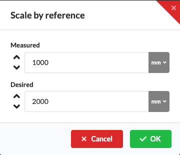
Scale selected objects based on a known length in the drawing. First select at least one object. Activate Scale, then select By Reference in the Toolbar. In the Renderer, click the two endpoints of a line with a known length. Production Assist enters the distance in Measured and then opens the dialog. Under Chosen, enter the desired length of the same line.
| Field | Effect and limitation |
|---|---|
| Measured | Length of the line between the two points clicked in the Renderer. You can correct the transferred value. If it is 0, no scaling is performed. |
| Chosen | Desired length of the same line. Enter a positive target measurement. |
| OK | Scales all selected objects uniformly along the X, Y, and Z axes using the ratio Chosen ÷ Measured. For example, a measured length of 1 m and a target measurement of 2 m double the object size. A message appears if no objects are selected. |
| Cancel | Closes the dialog without scaling. |
Enter a positive target measurement. For missing or non-positive values, the dialog does not show a field-specific error message. Check the resulting scale after selecting OK.
Use Rotate to rotate selected objects around the X, Y, or Z axis with the rotation handle of the coordinate system.

When rotating, select Global to use the drawing axes or Local to align with the object axes. Press Ctrl (Windows) or Control (macOS) to cycle through the available rotation anchors.
Use Align to aim spotlights at a point or move the origin of an Assembly Group.
With the Light option, align selected spotlights to a focus point set in the Renderer.
With the Assembly Group Origin option, align the origin of an Assembly Group to a point set in the Renderer. Object positions are relative to this origin.

Use Orbit to control the view in the Renderer. The Pan option moves the view without changing the objects. It can be useful when working on a touchscreen.

Use Measure Distance to measure a distance in the Renderer. Click the points whose distance you want to check. Press Enter or double-click to finish measuring; press Esc to cancel the current measurement. Press X to switch back to the Select tool.
Use Mirror to mirror selected objects across an axis that you define with two points in the Renderer.
Press Esc to cancel the operation.
Use Patch to connect consumers to a power distributor one after another.
If the distributor no longer has suitable free outputs, Production Assist can create another distributor of the same type. If a consumer has no free connections, it is not connected and a message appears. The complete patch workflows are described in Electrical Planning.
In the desktop app, select Camera in the Toolbar or on the right side of the Menu Bar. Both commands open the QR scanner, but use different dialog titles: from the Toolbar, the dialog is called Import QR Code; from the Menu Bar, it is called Scan QR Code. The current Toolbar with the camera tool is shown at the beginning of this chapter:
The QR scanner is the same dialog used by the Menu Bar. This current component screenshot shows the scanner view from Scheduled Maintenance; its title, Scan QR-Code from Object, differs from the Toolbar and Menu Bar titles. The audit example did not recognize a QR code, so the screenshot shows the current dialog with that scan status.
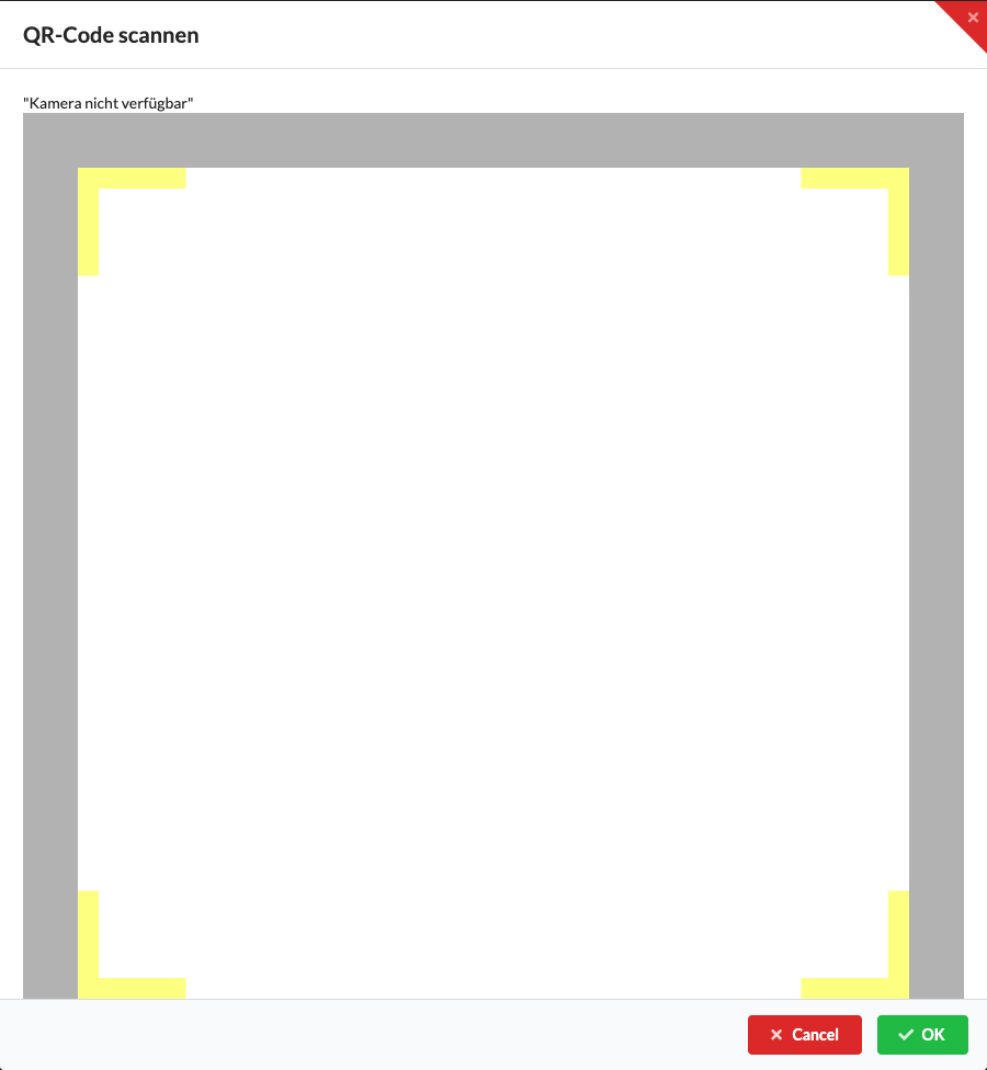
Point the camera at a QR code. The scanner processes Production Assist links to objects and Assembly Sheets. An object link selects the object in the online project; an Assembly Sheet link opens the Assembly Sheet. If both the user account and project differ from the currently open area, Production Assist attempts to open the link's Master workspace. Other QR codes are reported as unsupported links.
The camera must be available, and Production Assist needs camera access. After a supported link is scanned, the dialog closes automatically and the object is selected or the Assembly Sheet opens. An unsupported link displays a message; the scanner remains open. Close the scanner with OK, Esc, or the X in the top-right corner. If you opened it from the Toolbar, the tool switches back to Select. From the camera command on the right side of the Menu Bar, you return to the previous plan view. The linked object information requires an online-saved project and the appropriate access rights or a share link. For information about object QR codes, see QR Code in Object Properties.