

Version 1.15 brings planning and review closer together: trusses and chain hoists can be aligned more precisely, wind load areas and supports are easier to check, and calculation results are easier to trace. The revised beam and bridle view supports checking connected structures; additional formulas, reporting features, and CAD improvements make it easier to evaluate and share planning data.
The UI images were rendered from the current interfaces using synthetic sample data. They are provided for orientation; example paths, models, and numbers are not project results. Explanatory drawings are identified as diagrams.
Production Assist is also available for Windows as a portable app that does not require installation. Extract each portable version to its own program folder to use multiple versions in parallel. Each copy stores its user data in a separate folder beside the app, keeping the settings and local resources of the portable versions separate. The installed app can also be used in parallel. See Portable desktop app for information about user data, updates, and plugins.
When several CAD applications were open, it was not immediately clear which drawing the desktop app was working with. The mode selector on the right side of the footer now lists the available CAD connections. For example, select Vectorworks or SketchUp to connect the app to that application in Plugin mode. App switches back to standalone operation.
In Plugin mode, the footer displays the name of the connected CAD application and its connection status. This lets you check which connection is active before making a change. The selector is described in the User interface.
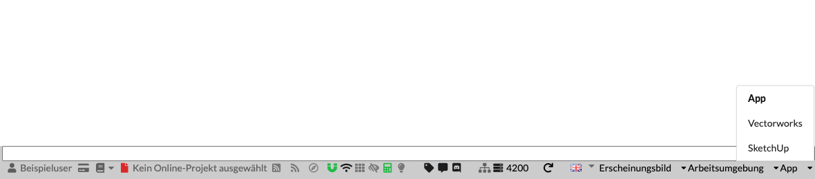
Example with two available CAD connections: select Plugin mode from this menu.
Mirrored objects no longer incorrectly appear black in the 3D renderer. This display issue could make visual inspection difficult even though the geometry was present. Symmetrical constructions can now be assessed more easily without redrawing objects just to make them display clearly.
The layout of the Navigation palette has been improved. Its clearer arrangement makes it easier to find your way between stories, classes, and other project areas, and reduces the time spent looking for entries. This helps you switch between tasks more quickly while planning. The tabs are described in Navigation.
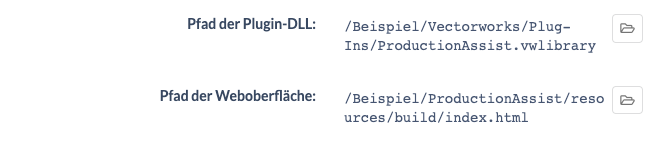
With multiple plugin installations, it could be unclear which copy the CAD application had actually loaded. About Production Assist now shows the plugin DLL path and the web interface path. Compare these with the folder you updated. The folder icon opens an available local path in the file system. This shortens troubleshooting when app, plugin, and UI versions differ. Open the dialog from the Help menu.
The app has a dedicated Pressure unit setting, including MPa and psi for material pressure and stress values. This means you no longer need to convert these values outside the application. The shared setting makes it easier to read and compare results in your preferred unit system. See Unit settings.
If a truss's object origin is away from the desired connection point, positioning it using only the origin is cumbersome. New handles in the 3D renderer let you move it directly by its structure. Grab the truss at the structural connection and align it with the intended connection point. This reduces the need for follow-up position adjustments; check the positions of the structural ends afterward.
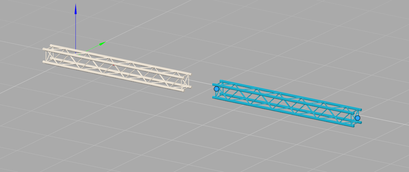
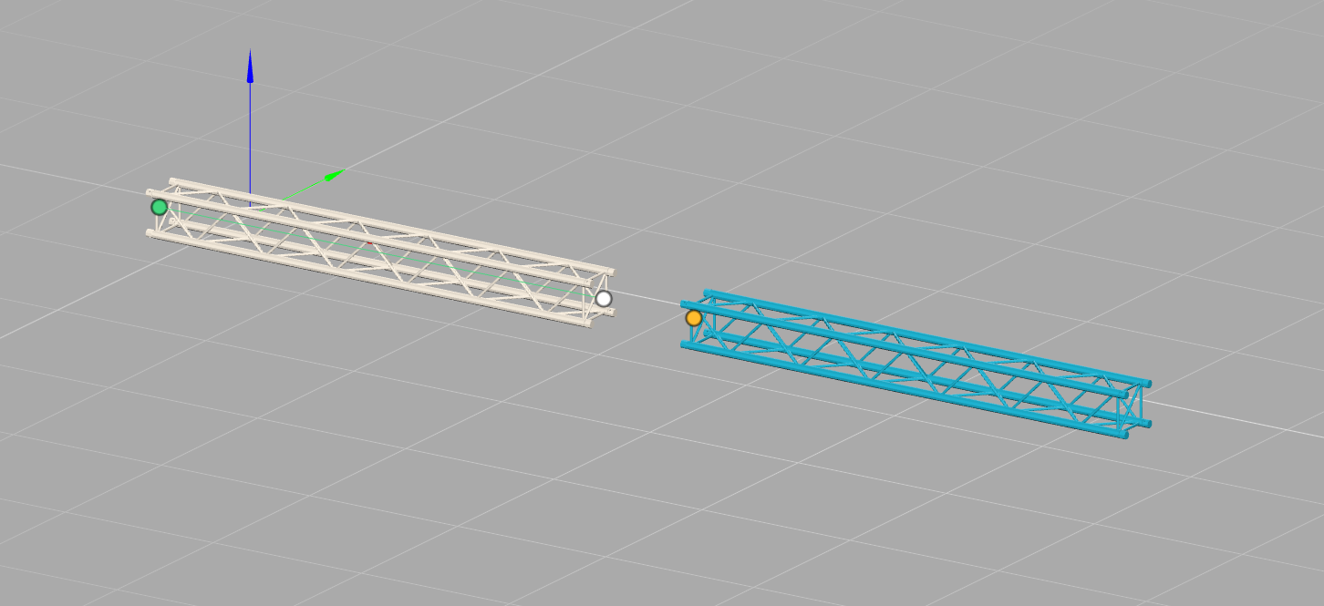
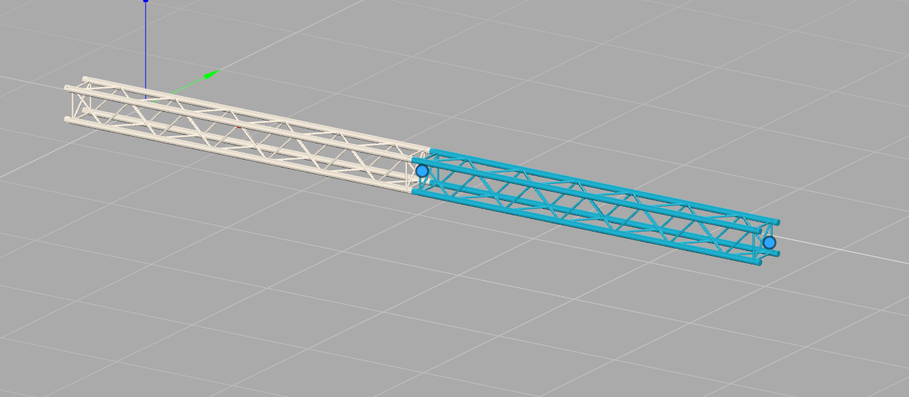
The images show the selection, handle operation, and aligned position.
The object origin of a chain hoist can also differ from the connection point that matters for suspension. New structural handles in the 3D renderer make it easier to position the chain hoist on the intended structure. You can align and check the connection directly in the model without adjusting the position using only the origin.
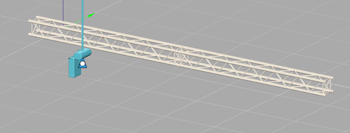
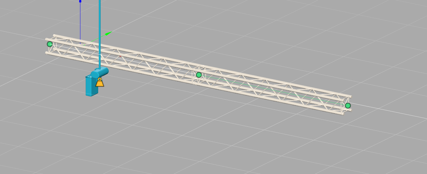
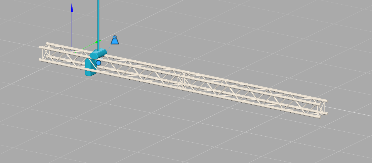
The images show the chain hoist before and after alignment at the structural connection.
Production Assist supports MCP, the Model Context Protocol, for connecting to a compatible AI assistant. The assistant can read data from the active drawing and call approved application functions. This saves repeated searching in tables, entering properties, and assembling reports.
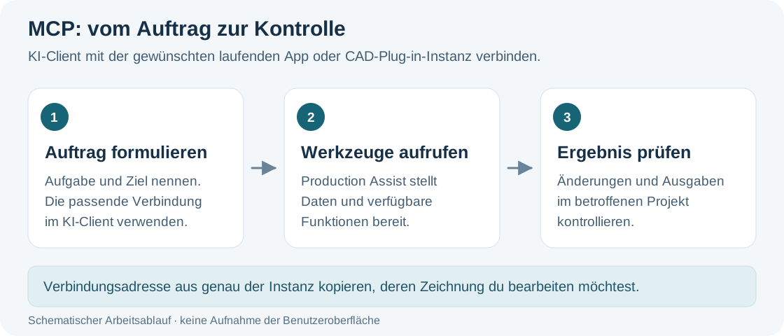
Copy the connection from the exact running app or plugin instance whose drawing you want to edit. Connect your AI client to that instance, then describe the task. Setup and available commands are explained in MCP connection in the user interface.
| Use case | Example request | Result and required information |
|---|---|---|
| Query loads | “Which loads are included in the drawing, and what is their total weight?” | The assistant reads the load summary and explains the recorded load components. The calculation must be complete for current results. |
| Check safety factors | “Which safety and load factors does the active load combination use?” | The assistant reads the configured factors and associates them with the active combination. The query alone does not assess whether they are suitable for your project. |
| Set wind load | “For this wind load area, set the agreed wind speed and the specified profile.” | The assistant can edit wind load data. Specify the area, location or profile, and values clearly; check the resulting loads. |
| Build a structure from a sketch | “Recreate this sketch as a truss structure; ask about any missing dimensions and components.” | An image-capable AI client can interpret the attached sketch and rebuild it with the modeling tools. Dimensions, resources, and connections must be clarified; MCP itself does not interpret images. |
| Build a structure from a description | “Create an 8 m truss line at a height of 6 m using the truss type I specify.” | The assistant can find, import, and place suitable resources. Add supports, loads, and connection details for a complete calculation model. |
| Insert chain hoists | “Place two chain hoists of the specified type at these suspension positions.” | Existing or imported chain hoist symbols can be inserted at explicitly specified points. Check connection heights, capacities, and load assignments. |
| Find unusual results | “Show me members with high utilization and their associated messages.” | The assistant can read calculation results and errors and identify affected objects for further checking. |
| Edit bridle material | “Which parts are specified for this bridle? Replace the part I name.” | The assistant can query and change materials and assignments. Changes to a shared material set affect all associated bridles. |
| Create a structural report | “Create a calculation report from the current results, with a project description and verifications.” | The assistant can read report context and results, draft a report, and initiate preview or PDF output. Missing project information must be added and the finished documents checked. |
You no longer need to download packages for every CAD application in advance. The installation dialog shows detected target applications and versions. Select only the entries you need; Production Assist downloads the required plugin packages. If the same package is used for several selected targets, it is downloaded once for all of them.
During the download, the app shows the package name, amount of data transferred, speed, and estimated time remaining. When the total size is known, percentage progress is also shown. You can cancel the download. Installation follows. First close the relevant CAD application; running applications are shown in the dialog and cannot be selected for installation. Check the targets again after closing it. The full process is explained in Download and installation.
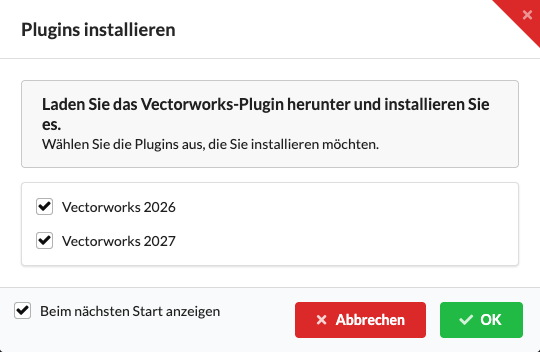
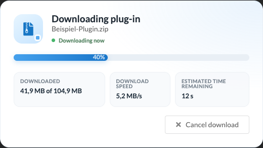
Example data: target selection and download display are separate steps.
The Production Assist browser editor has been revised. The improvements make it easier to edit a shared online project and reduce friction when switching between the project view and editing. The actions available to you still depend on your access. See Online projects in the browser.
When connecting two structures, the connection type must match the real construction. In the 3D renderer, the modes under New Object → Connection are now arranged more clearly with icons. You can select the required type directly instead of distinguishing similar connection actions by their text.

| Mode | When to use it |
|---|---|
| Rope | For a tension-bearing rope connection between connection points. |
| Truss Cross | For a crossing connection between structures; choose the Truss Cross type that matches the construction. |
| Drop | For a vertical connection between structures positioned one above the other. |
| Pipe | For a pipe connection with a suitable cross-section. |
| StackTrusses | For trusses stacked on top of one another. |
| Bridle 2 Leg / 3 Leg / 4 Leg | For a multi-leg suspension with the corresponding number of upper suspension points. |
After selecting a mode, set the corresponding connection points. Check the connection type and position in the model. Connections describes the basics, and Truss Crosses covers the crossing variants.
For evenly spaced components, the same distance had to be determined repeatedly. The dedicated Paste Offset panel keeps the X, Y, and Z distances and their copy actions in one place. Open it using Window → Paste Offset.
Enable Auto Paste Offset adjusts the distances to the extent of the selected structural geometry. This helps line up suitable components directly. Use Rotate 180° and move to X+ to create a rotated and offset copy.
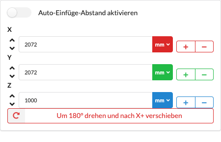
Paste offset is also available in CAD workflows. The native copy and move commands in AutoCAD and BricsCAD, SketchUp, and Vectorworks use the corresponding axis distances. This lets you create regular arrangements directly in the host application. The native commands also support moving; the panel's plus and minus buttons duplicate. Paste Offset explains the details.
The 2D and 3D renderers have been revised to reduce loading times and make navigation smoother in large drawings. This is intended to reduce waiting when opening a drawing and when rotating, zooming, and panning the view.
The following figures are explicitly placeholders and are not measured performance data. The improvements are calculated only from these example values; measurements are still needed for a reliable before-and-after comparison.
| Measurement on the same large reference model | Placeholder: before version 1.15 | Placeholder: version 1.15 | Improvement calculated from placeholders |
|---|---|---|---|
| Load a drawing in 3D until it is usable | 10.7 s | 2.72 s | 74.6% shorter loading time |
| Load a drawing in 2D until it is usable | 14 s | 4 s | 71.4% shorter loading time |
| Frame rate while navigating a large 3D drawing | 8 FPS | 120 FPS | 15 times the frame rate |
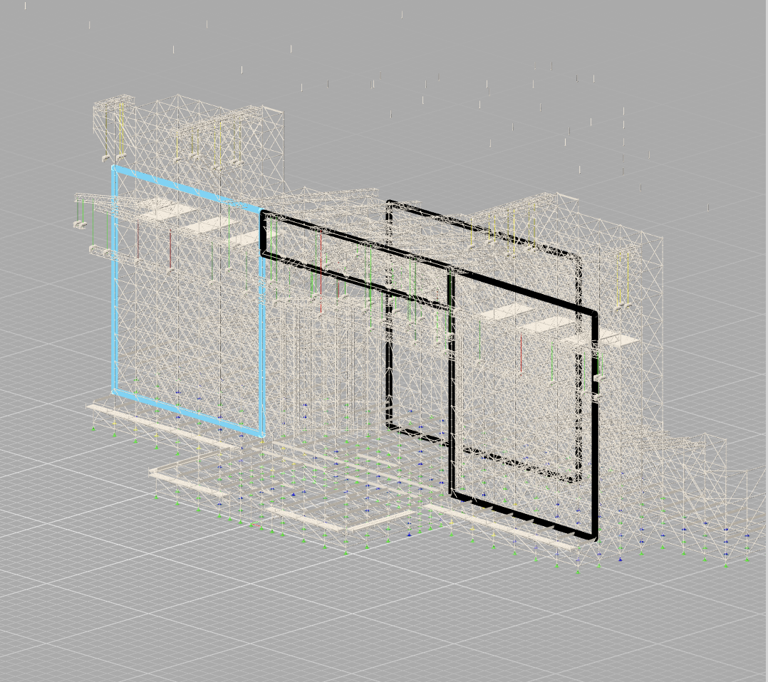
Specified test system: macOS 26, Apple M4 Pro, 48 GB RAM. The reference model contains 9,191 Layer Scaffolding objects with inserted calculation results.
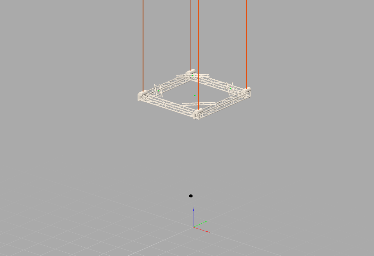
Hidden connections in densely populated models can be difficult to inspect when many objects have to be hidden individually. The improved cutting plane exposes these areas in the 3D view. You can enable it in Quick Settings and set its offsets and rotation. The cut view changes the display; turn off the cutting plane to return to the complete model. Drawing and renderer explains the procedure.
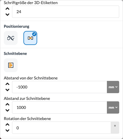

Part of the scrollable panel. The two offsets limit the visible area.
The support chat can use the current clipboard contents for pasting. This makes it easier to add a copied screenshot to a problem description without first saving it as a separate file. It helps clarify a visible problem and reduces the preparation needed for a support request.
A bug that occurred when switching to editing mode with a filter active has been fixed. A filtered view is no longer affected by this bug when starting object editing. You can narrow down the selection and then edit the required content without having to remove the filter as a workaround.
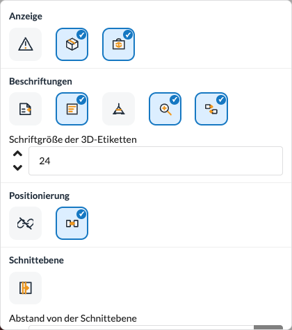
Frequent display changes should not interrupt model control. Quick Settings now group their switches more clearly into categories such as Display, Labels, Positioning, and Cutting plane. Active icons are highlighted. This makes it quicker to see which displays are enabled and, for example, change labels for a detailed inspection. Drawing and renderer explains the options.
A bug when switching the application language has been fixed. Language switching is no longer affected by this problem. This makes it easier to work at shared workstations and switch to your preferred language without encountering a faulty interface state.
When all panels are closed, the controls needed to continue working are unavailable. In this situation, Production Assist now displays a help message with the Reset UI button. Clicking it restores the default layout so the renderers and palettes are accessible again. The User interface describes the procedure.

Object properties were harder to read and use in narrow panels. Object Properties now adapts the arrangement of its contents better to the available space. You can therefore use its fields, grouped by property, alongside other open panels. Which groups appear depends on the selected object. Object Properties explains the fields.
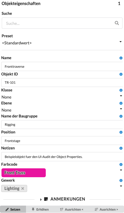
Example of a narrow palette; scroll to access the remaining groups.
A name alone does not reveal whether an entry is, for example, an assembly, a truss, or a chain hoist. The Scene Tree supplements the hierarchy with clearer type icons. This helps you identify and select entries with identical or similar names more quickly. Expanding an entry still shows its contained objects; the type display does not replace checking the properties. The Scene Tree explains selection, filters, and hierarchy.
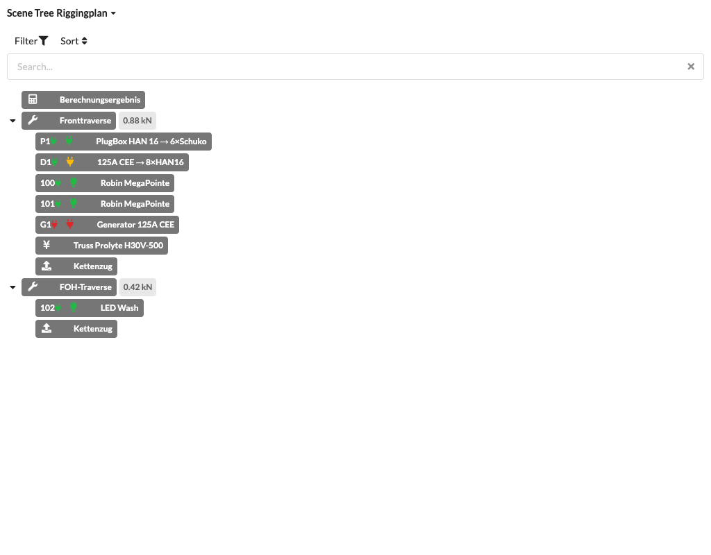
App view showing the type icons in the object list.
You can now move the support chat window. Drag it to a convenient location and keep the chat open while the relevant area of the model remains visible.
The diff view now compares changes more quickly. This makes it faster to review differences between drawing versions.
Sign-in through Single Sign-On (SSO) has been improved. Organizations with SSO configured can therefore use Production Assist more reliably through their central sign-in service.
Authorized Production Assist trainers can now issue trainer vouchers. A voucher is tied to an email address and, after confirmed redemption, provides a three-month trial period. Trainer vouchers describes the requirements and process.
The website header shown after signing in arranges navigation, language selection, and account functions more clearly. You can access QR scanning, account settings, and sign out on the right side of the header. This makes it easier to move between website areas and account management without first searching the page for the action you need.

The email for a completed calculation now contains a direct link to the report; its wording has also been revised to make the next step clearer. You no longer need to go through Production Assist and look for the download there. You can reach the finished document more quickly and use it more easily for further work. Request a reviewed structural calculation explains the procedure.
Uploading projects to the engineering office has been made more robust. This reduces disruptions when handing over the project data needed for a calculation. A request can therefore be prepared and submitted more reliably; continue to check the confirmation and request status displayed.
Templates for self-weight and area loads can be used together. Both load components no longer need to be handled as separate template workflows. This simplifies the preparation of recurring loads. When combining templates, check the applied loads so that the same component is not accidentally counted twice.
The scaffold components have been improved. This supports using these components in a single structural model and reduces rework when preparing the model. Continue to check the recognized members and connections after importing them. Preparing Layher and custom symbols describes a suitable workflow.
In an overall spatial view, loads and support points are not always clearly associated with a beam. The redesigned Beam View displays selected structural elements along their length. This lets you follow load positions, supports, and result diagrams on the same component and check input positions more precisely. Beam View explains how to use it.
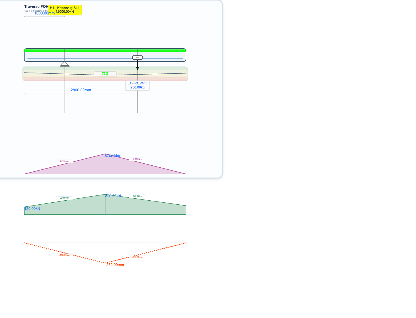
App view of Beam View with an example beam, a support, and a load.
3D renderer view of the example model with a 5 m truss, two chain hoists, and a VL2600 spot fixture. The example data is for orientation and is not project results.
Schematic illustration with example positions, not a screenshot of the user interface.
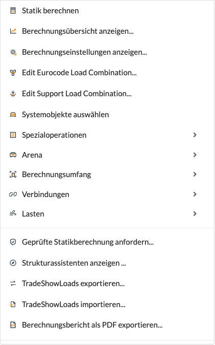
Additional icons in the Rigging menu make it easier to find calculation and checking actions. For example, you can distinguish Calculate Structural Analysis, the calculation overview, and the commands for the calculation scope more quickly instead of reading the entire menu each time. The Rigging menu explains the individual actions.
Autofix can now also apply the second correction option offered. For messages with multiple possible solutions, another suitable repair is now available directly. This saves manual intermediate steps. Choose the technically correct option, then check the model and the new calculation. Troubleshooting explains messages.
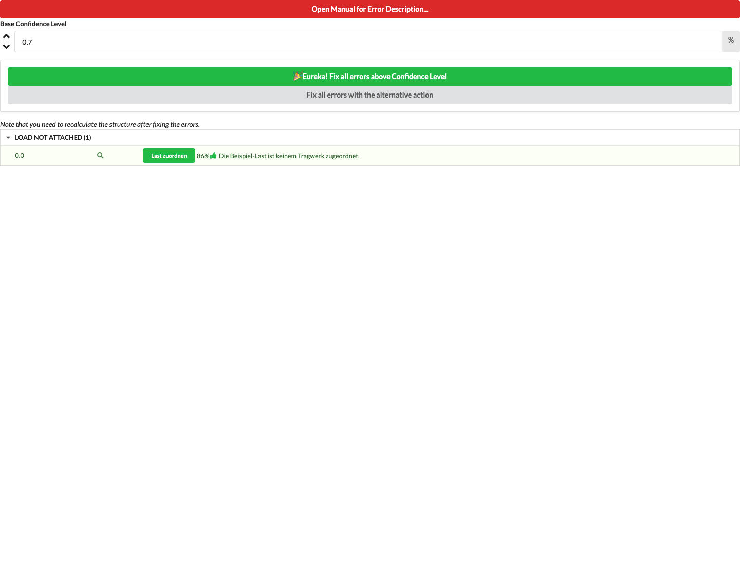
Excerpt from the error list showing the second correction option.
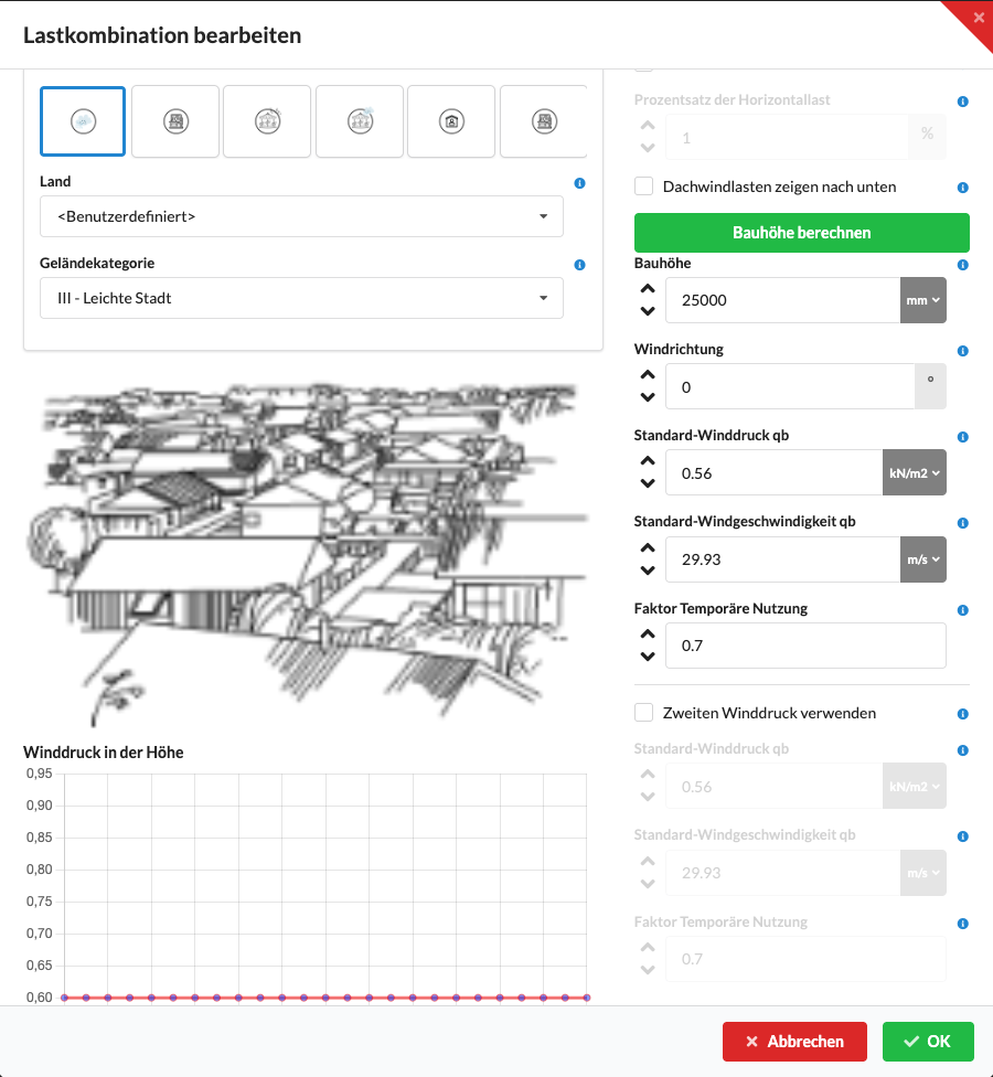
Wind loads depend on several inputs and factors. The redesigned wind load interface groups these values and their explanations more clearly. This makes it easier to check the assumptions of the active load combination before using the calculated wind forces. Wind loads explains the relationships and supported profiles.
A new mode automatically generates wind load planes for Aluvision components. This reduces the manual creation of corresponding areas when preparing the model. Check the generated areas and their assignment before using the results. The Aluvision trade show booth provides an example.
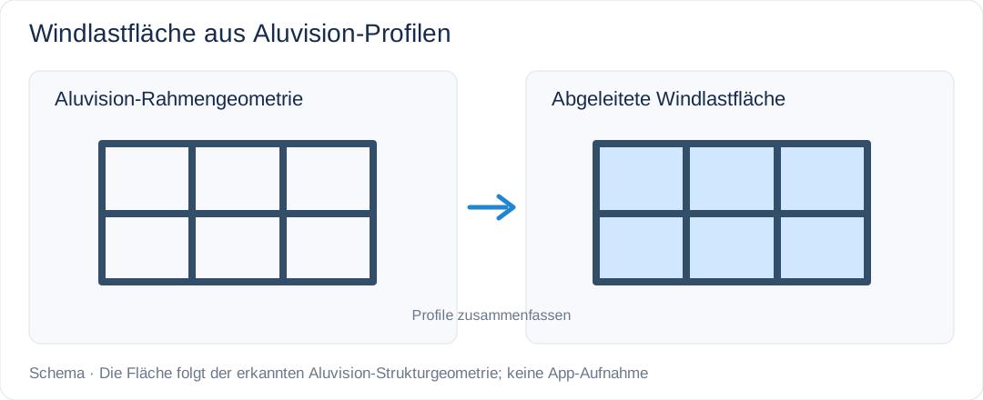
Schematic comparison of the frame geometry and the derived wind load area; not an app screenshot.
Automatically generated supports and their display in 3D labels have been improved. This makes it easier to associate the calculated reactions with the automatically assigned support points. It helps you check the load path without having to look up all values only in tables. Structural calculation explains the display.
Positive and negative regions of influence lines are now also distinguished by color. This makes sign changes easier to recognize without having to infer each region from numbers and curve position alone. The colors depend on the result quantity; for example, positive and negative regions of bending moment use different colors. The values and local axis reference remain authoritative.
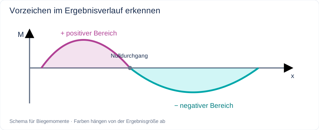
Schematic curve without project values; the + and − markers indicate the signs in addition to color.
An additional ANSI interior option expands the available wind load profiles. This lets you configure suitable interior cases directly instead of manually reproducing an approach intended for another case. Select the profile only if it suits the project requirements. Choosing a wind load type and location explains the available profiles and their limits.
In addition to the formula, the verifications in the calculation report now show the values actually used. This means you need to gather inputs and results from different tables less often. It makes it easier to follow the calculation and coordinate the documents. The output is explained in Calculation Report.
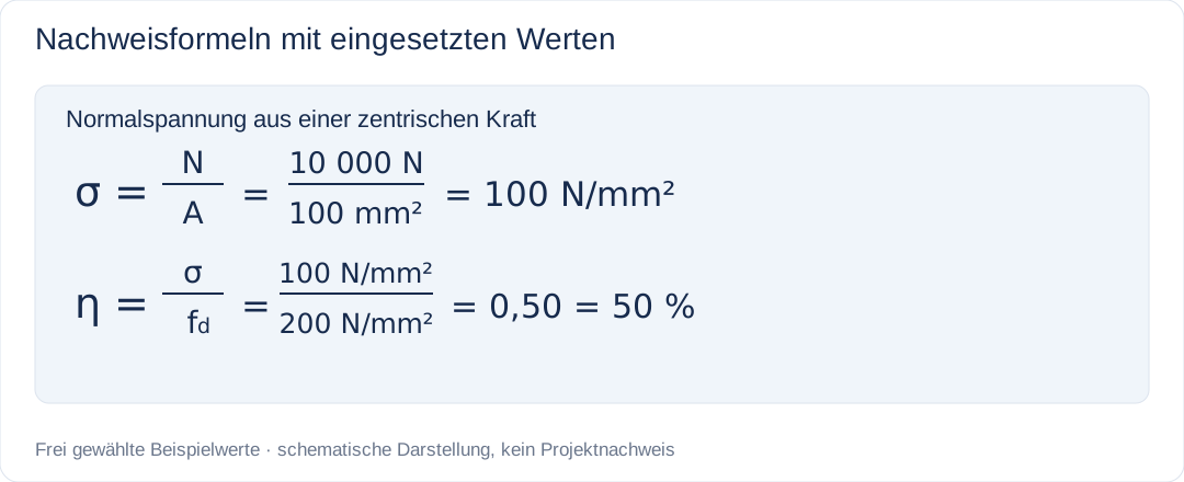
Simplified example with freely chosen numbers; not an actual PA verification.
Cross-section generation now also supports ladder trusses. This means this design can be included in the intended generation workflow instead of resorting to an unsuitable different truss type for the cross-section data. This simplifies preparing suitable resources. Check the generated values and the actual truss design.
The workflow for Truss Cross has been improved. Connections between crossing structural members are now easier to prepare and check. This reduces detours when modeling overlapping structures. The selected connection type must still match the actual connection. The options are explained in Truss Crosses.
Roof areas can be included in the model with their geometry and the intended roof wind load approach. This reduces the need to manually recreate roof loading using individual substitute loads. Check the area, slope, covering, and load direction. Roof area: stage roof explains the supported roof modeling.
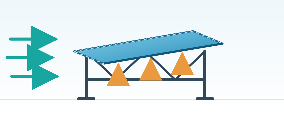
Schematic roof model; the settings must match the actual roof structure.
Ballast calculation now accounts for automatically generated supports. This makes it possible to assess the required ballast values there without first creating each support point manually. This simplifies planning ground support systems. The actual ballast arrangement and force transfer must match the model. See Calculate ballast.
Report creation through AI chat has been improved. This makes it easier to combine project data and a report draft into understandable documentation, reducing the manual effort involved in writing. Check suggestions, verifications, and the finished output before using them. The AI report writer explains setup and workflow.
When a force acts at a distance from the connection point, it also creates a moment. The calculation accounts for this offset, so eccentric loads and their additional effects are captured in the model. Check the position, center of gravity, and load offset: a load entered only at the center does not fully describe the same setup. Loads in structural calculation explains the inputs.
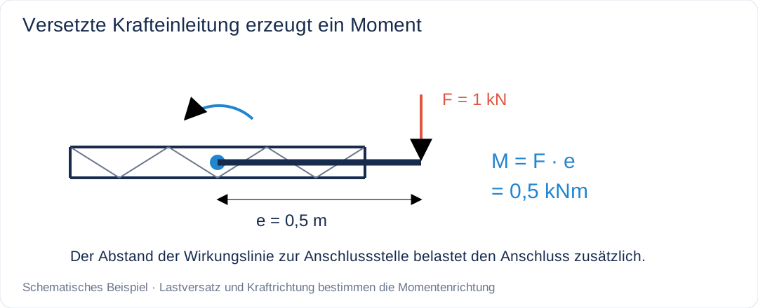
Simplified example: moment = force × perpendicular distance of the line of action.
Structural lines defined in a drawing can be saved as defaults. This means recurring assignments do not need to be set up again for each new plan. This speeds up preparation of similarly structured CAD drawings. The related options are described in Settings.
Additional formulas in the Calculation Overview make the basis of a result available directly while checking the model. You do not need to export a PDF report every time to get an initial explanation of a verification. This makes it easier to read the formula, substituted values, and utilization together. The overview is explained in Structural calculation.

App excerpt with rendered formulas and synthetic example values.
The 3D view has better touchscreen support. This makes it more comfortable to inspect the spatial model on touch-enabled devices. It reduces interaction barriers in meetings or when checking a plan on a suitable touch device, and makes it easier to switch between overview and detail.
For transferred position data, it is important to see whether values are being sent or received. The PosiStageNet indicators distinguish between server and client; their histories provide access to the latest transferred values and log messages. This lets you check the data direction and incoming positions instead of judging missing movement only from the model. The PosiStageNet guide explains setup and requirements.

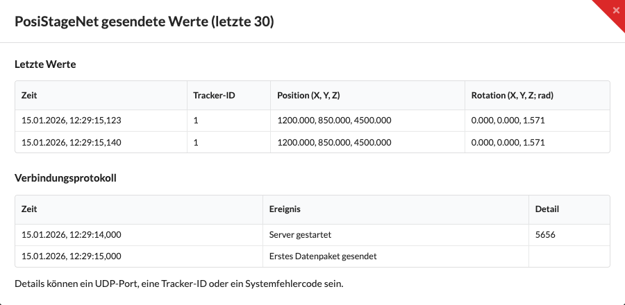
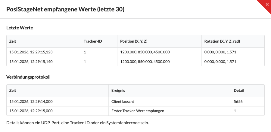
The PSN switches are in the footer; the histories show example values and separate logs for sending and receiving.
The assumed wind pressure is now visible in the load overview. This makes it possible to check the associated wind loading alongside the loads instead of having to look up the pressure value in the settings. This speeds up plausibility checks of inputs and results. See Check wind loads.
The coordinate overlay helps with spatial alignment, but can obscure the view during a presentation. You can now turn it on or off using Show coordinates in 3D renderer in the renderer settings. This lets you switch between an orientation aid and a less obstructed model view. The option changes the display, not the object coordinates. See Renderer settings.

When only part of a drawing is calculated, the results must not be confused with a calculation of the entire drawing. The Scene Tree now marks a defined calculation scope directly in the object list. This helps you recognize the limited scope when selecting and checking objects. Also check selection, visibility, layer, and class filters. The settings are explained in Calculation scope.
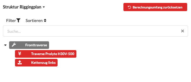
Prerig trusses are displayed correctly in the calculation overview. The previous display error no longer makes it difficult to associate these trusses with the results. This makes it easier to check a plan using prerig systems and reduces unnecessary questions about the display.
Dual language report lets you output automatically generated report text in two languages. This reduces the manual editing needed to coordinate with international participants. Custom text and project descriptions are not translated automatically; formulas and result data appear once. Setup is explained in Bilingual report output.
For rotated truss lines and spatially offset loads, the position of the force relative to the local structure is decisive. Center of gravity calculation and accounting for rotation have been improved. These relationships are therefore captured more accurately in the calculation model. After making changes, check the cross-section orientation, center of gravity, and load offset together.
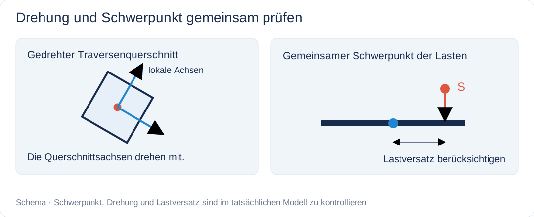
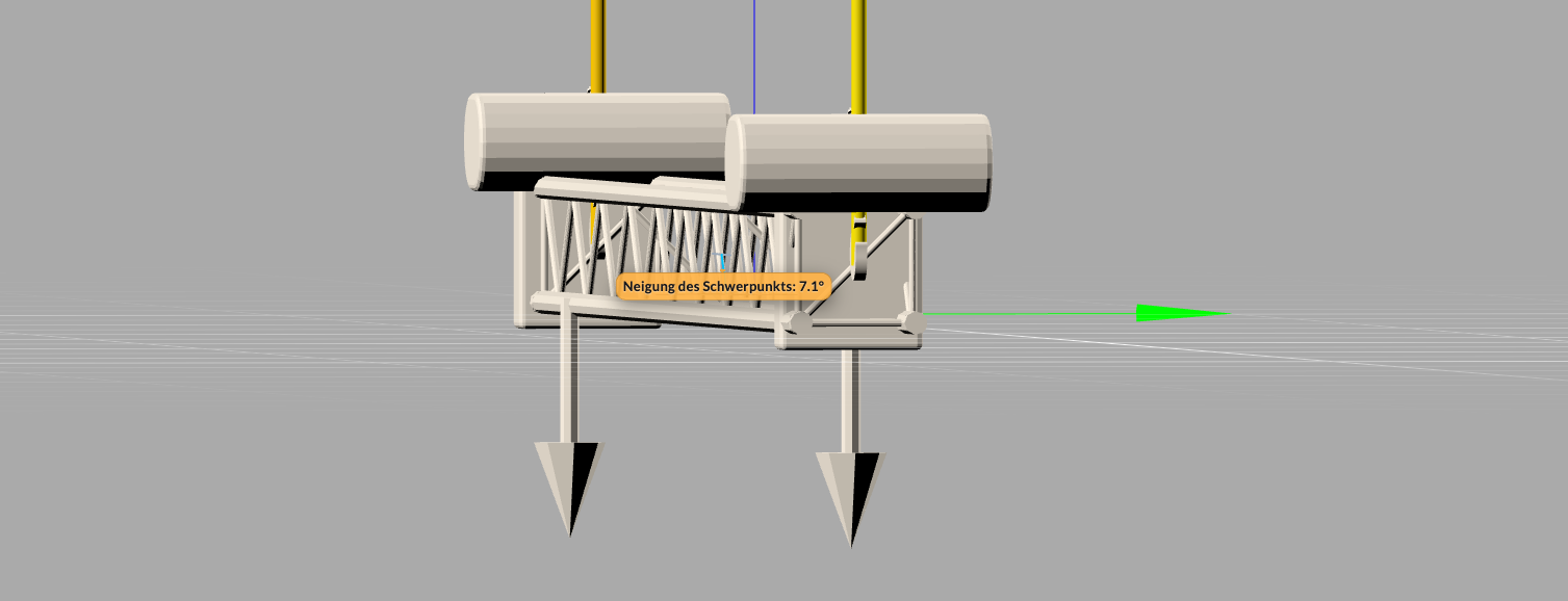
Diagram: The cross-section axes rotate with the truss; the position of the load's center of gravity affects how the force is applied.
With a Ground Support, results must be traced across columns, cross trusses, and their connections. The improved Beam View makes it easier to identify the components involved and their connected structures. This lets you check transitions more directly instead of looking for every result path only in the overall 3D view. Beam View explains how to use it.
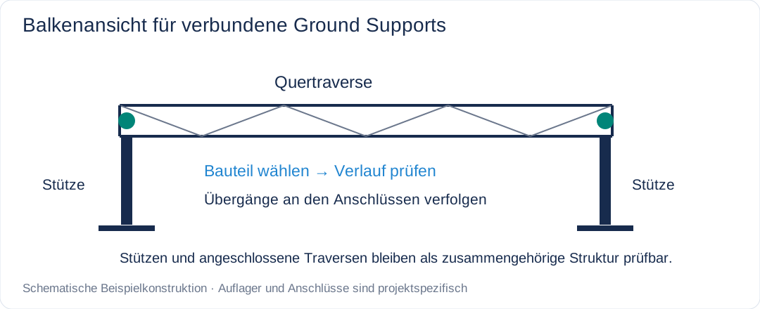
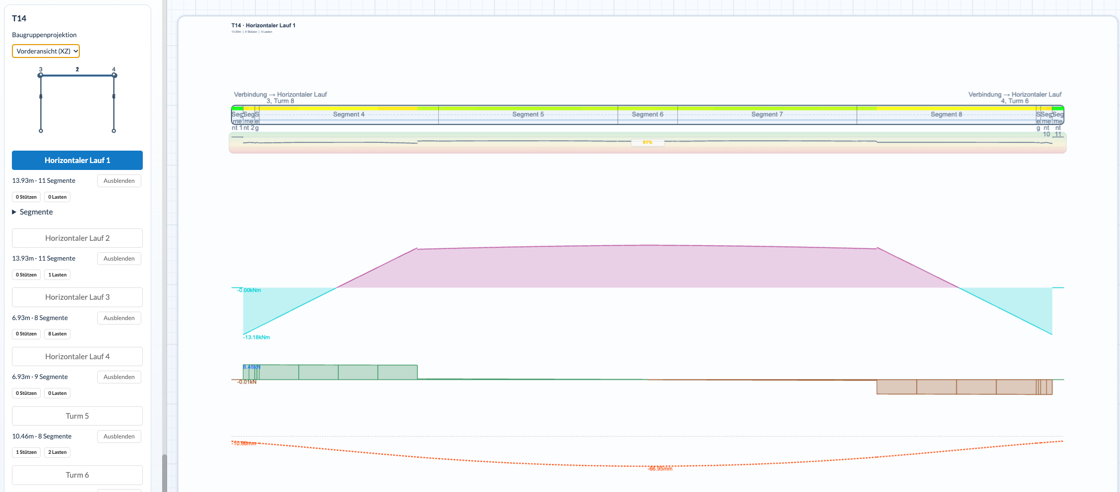
3D renderer view of the example model with a Ground Support tower and attached trusses. The view is for orientation and is not project documentation.
Schematic example structure; beam checking must account for the actual connection conditions.
A connection does not always behave like a rigid connection or a spring with constant stiffness. Nonlinear joints allow a piecewise linear characteristic curve for force or moment as a function of displacement or rotation. This can represent, for example, a clearance range before force begins to build. Choose a characteristic curve that matches the actual connection and its local axes. The options are explained in Object Properties.
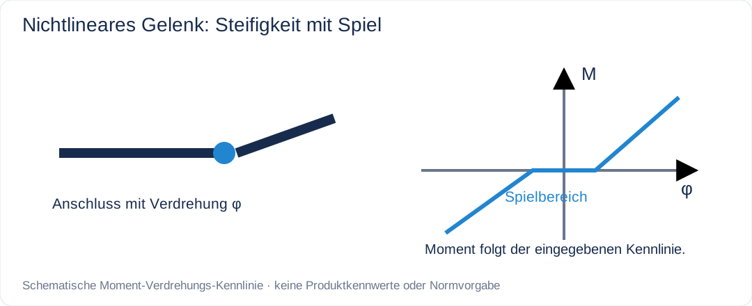
Functional diagram only, without product values. A characteristic curve does not replace a capacity check of the connection.
In compression-loaded structures that are sensitive to deformation, deformation also changes the effect of the forces. The improved calculation using second-order theory accounts for this effect. A simple example is a column deflected sideways: the additional distance from the line of action of the compressive force creates another moment. The calculation method and model assumptions must suit the task. See Structural calculation.
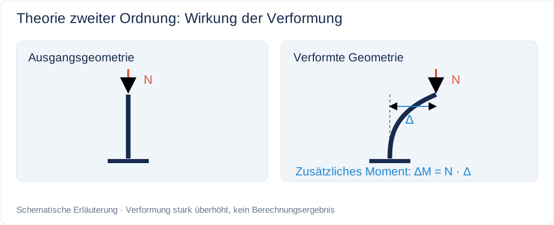
Deformation is schematic and greatly exaggerated. The graphic explains the effect and is not a stability check.
The Aluvision Linear cross-section profile has been corrected. Corrected cross-section data are now available for this profile; an incorrect profile basis no longer complicates the calculation in the same way as before. When updating existing projects, check the resource used and recalculate affected structures.
The Deform workload display based on deflection option allows the workload display to remain straight, even when a deflection has been calculated. This makes it easier to read result paths in the renderer and CAD plug-ins. The option changes the display, not the calculated deformation. More display options are available under Renderer settings.
Deflection values now use the page length unit. This gives you better control over how deflection is displayed.
You can now visualize where influence-line results are used as floor loads.
If errors occur after cable or support failures and the structural system becomes unstable, error handling has been improved. This makes it easier to interpret these calculation states and troubleshoot them afterward.
The new Show FEA diagnostics setting shows or hides technical FEA solver diagnostics in the error list and drawing. These messages help investigate matrix errors and unstable stiffness; the setting does not change the calculation itself. See FEA solver diagnostics for details.
Hide load table explanation in structural reports lets you hide the automatically generated explanatory text below load summaries in calculation reports. The load tables and text you have written yourself remain. This lets you adjust the amount of automatically generated report output. The setting is under Structural settings.
The menu bar in iOS has been improved. Commands are now easier to find and recognize on the mobile screen. This reduces friction when switching between available functions and makes Production Assist easier to use on an iOS device.
The display on iPhone has been revised so that content and controls are easier to see and use on the smaller screen.
The iOS app starts faster. This lets you resume working with Production Assist sooner after opening it.
The iOS app now supports PosiStageNet (PSN).
New widgets for iPhone and Apple Watch show calculation results directly on the respective device. This lets you view the results at a glance without first opening the app.
A new truss calculator enables simple calculations directly on iPhone. This makes a compact calculation workflow available while on the go.
A new Bridle calculator enables simple Bridle calculations directly on iPhone. This lets you quickly perform basic calculations while on the go.
The Production Assist Core API supports definitions for Ground Supports. Connected programs can use these to describe these supports directly in the model they pass on, rather than having to add the information outside the model. This makes it easier to transfer more complete structural data. The interface is described in Production Assist Core.
A new standalone Bridle calculator complements the Bridle tools and enables simple calculations in a separate workflow.
Bridles can now be generated automatically for selected loads. This speeds up setup when several loads need Bridles.
A new Bridle dialog combines the view of the rigging arrangement with the assembly of its parts. Dimensions and material assignments no longer need to be considered separately. Check the parts preview and apply changes selectively. This makes it easier to move from planning to material preparation. The Bridle View explains how to use it.
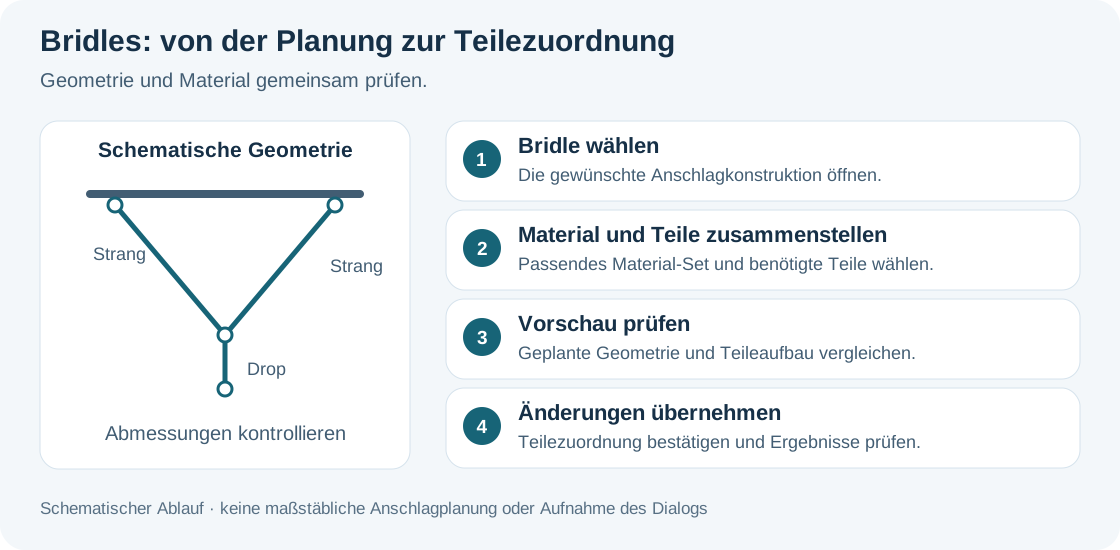
The graphic shows the work steps. It is not a to-scale rigging plan or an image of the dialog.
When the Bridle Material Engine is enabled, Production Assist automatically checks equipped Bridle legs, including Drop, in the background against the 3D geometry of other objects. The check accounts for newly assembled rope paths and manually assigned legs. It also runs when static live calculation is off and helps detect obstacles along the rope path early.
The Bridle settings let you set a safety clearance for all Bridles. The default is 100 mm, measured from the straight rope axis to the 3D surface of other objects. At 0 mm, only actual collisions are checked. Apply changes with OK.
If there is a collision or a conflict with the safety clearance, the Material Engine first tries to rebuild the Bridle using the available parts at another suitable connection point. It applies only an arrangement with sufficient clearance within the permitted length deviations. The upper attachment points and the lower load point are retained; fixed rope selection, manual part assignments, and the setting for automatic assembly remain binding. Only if no suitable rebuild with sufficient clearance is possible does a message appear identifying the affected object and a position in the error list.
The check uses the straight rope axes and existing 3D meshes. Objects to which the respective leg is connected at its start or end are excluded even when a safety clearance is set; other obstacles along the rope path are still checked. Rope diameter and the actual wrap around the Basket are not assessed. Check rope paths for collisions and safety clearance explains the prerequisites and further limitations.
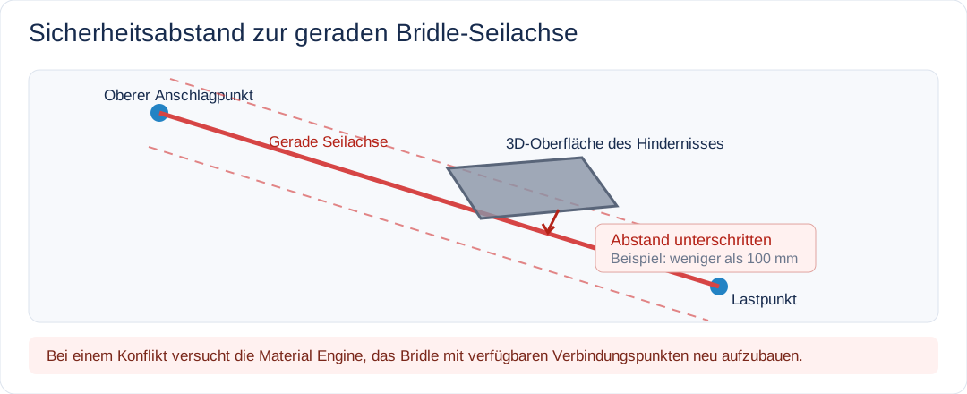
Schematic illustration of the safety clearance from the straight rope axis; rope diameter and wrapping are not shown.
When exporting, labels on a truss are always arranged starting from the Stage Left end. As a result, the order always starts on the same side, regardless of the previous sort order.
Labels are now sorted using their position on the truss, making them easier to follow in the drawing.
Until now, mathematical explanations had to be prepared as plain text or as a separate image. The report editor now supports formulas typeset with LaTeX. Click Formula, enter the expression in the Formula Editor, and apply it with Insert. The editor places the expression between two $$ lines. Then update the report and check the PDF output. This makes readable formulas easier to include directly in the report. See Writing Markdown and formulas for details.
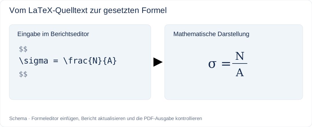
Schematic example: the LaTeX source becomes a typeset formula; this is not an additional calculation.
When calculation reports are exported, a graphic matching the dimensions is added for pipe cross sections. This makes it easier to compare the cross section used with its dimensions. This reduces questions about the profile shape and makes the calculation documents easier to read.
The support overview offers a filter for Bridles and improved table labels. This makes it possible to show the required supports more selectively; ambiguous columns make assignments less difficult. This simplifies the preparation of clearer rigging documents. Worksheets describes other table functions.
Calculation reports now support Markdown bulleted and numbered lists. This makes it possible to structure notes and work steps clearly; the list structure is also preserved in PDF output. Details are available under Writing Markdown and formulas.
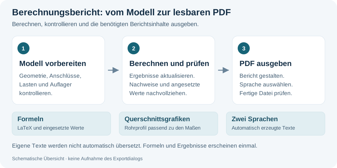
Schematic overview of report output; selecting a language does not automatically translate custom text.
The Production Assist user interface is now also available in AutoCAD for macOS. This makes it possible to use the integration in this host environment with its intended interface.
The following changes apply to the DWG integrations. An explicitly named host, such as AutoCAD or BricsCAD, limits the respective entry to that application. Setup and tool reference are available under Production Assist for AutoCAD, BricsCAD, and ZWCAD.
The integration is extended to support BricsCAD 2027. Plans using this host version can therefore be incorporated into the intended Production Assist workflow. This makes it easier to switch versions without having to stay on an older BricsCAD release solely for the integration. Use the plug-in that matches the host version.
Native commands such as PACX copy or move selected blocks by a defined offset. Recurring positions no longer need to be placed with the mouse each time. This simplifies even arrangements. Native Copy / Move explains selection, axes, and repetition.
A new point load can be given a suitable block representation as you insert it. This means you do not have to adjust the load graphically afterward. Start Insert Point Load or PAInsertPointLoad, set the insertion point, and use the command-line options.
| Symbol / Command | Option | Effect |
|---|---|---|
 Insert Point Load | Name | Sets the name of the new load block. |
PAInsertPointLoad | Weight | Enters the weight with a unit, for example 50 kg. |
| Symbol | Selects an existing block as an additional representation of the load. | |
| Enter / Create | Creates the load with the properties currently displayed. |
If no symbol is selected, the regular point-load representation remains available. After insertion, check the weight, position, and connection to the supporting structure. See DWG integrations for the tool reference.
Existing drawings often contain blocks with geometry but no weight value. With Add Weight to Block or PAAddWeightAttribute, you can add or update the WEIGHT attribute on existing block references. The blocks do not need to be redrawn.
| Symbol / Command | Input | Effect |
|---|---|---|
 Add Weight to Block | Select existing block references | Uses a preselection or prompts you to select references. |
PAAddWeightAttribute | Weight, for example 50 kg | Assigns the entered weight to each selected block reference; it is not a total weight distributed across the selection. |
| Enter at the weight prompt | Accepts the suggested value shown. |
The command line reports how many references were updated and, where applicable, skipped. Synchronize the drawing and check the weight and load assignment in Production Assist. The attribute alone does not create a load-bearing connection.
Synchronization with the active DWG drawing has been improved. This makes it easier to match the CAD file currently being edited with the Production Assist model. When several drawings are open, it reduces mix-ups and helps confirm that changes reach the intended model.
The Production Assist Library can be installed separately from the app. Existing library versions are easier to keep using when changing versions, instead of having to reassemble their components. Install Library and Check Library are available in the DWG workflow; in AutoCAD, Browse Library or PALibrary opens the library browser. Select the folder containing the DWG library files. The CAD quick start explains setup and host differences.
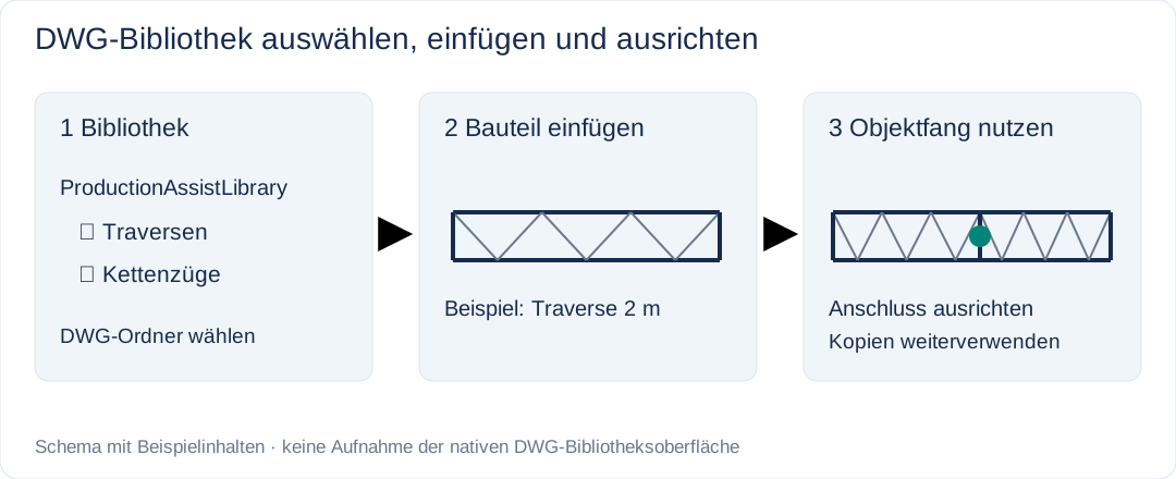
Schematic workflow with sample contents; not a screenshot of the native DWG library interface.
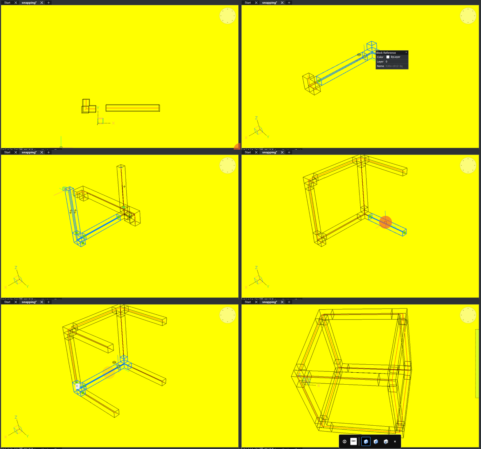
After insertion, you can continue using library blocks with the CAD host's snapping and alignment functions. In BricsCAD, F3 toggles ESNAP object snap; Shift + right-click opens additional snap options. For recurring components, you can duplicate a placed block and align the copy. The Snapping section explains the settings.
The CAD display supports utilization values along the calculated deformation shape. This lets you view stress and deformation together in space, instead of having to mentally match their positions. This makes it easier to check results. If needed, deformation can be turned off in the renderer settings.
Error labels can contain multiple lines. This makes longer notices easier to read in the CAD model instead of displaying them in one difficult-to-scan long line. It simplifies matching a message to the affected component and makes it easier to correct the drawing step by step.
The ribbons in BricsCAD have been revised. Production Assist commands are therefore easier to find and identify within the CAD interface. This reduces the time spent looking for tools when switching between drawing, connecting, and checking. See the CAD quick start for instructions on loading the interface.
AutoCAD supports automatically loading the associated CUIX menu file. This means the Production Assist interface does not have to be fully added by hand each time it is set up. This makes the commands easier to access after loading the plug-in. Setup is described in Load the plug-in and tools in AutoCAD.
The BricsCAD DLL now contains a version number. This makes it easier to identify the plug-in version directly from the file and compare it with the installed version.
An issue with handling empty blocks has been fixed. These blocks no longer interfere with importing a drawing because of this issue. Existing DWG files can be reused more reliably without having to clean up empty entries just to work around the issue.
Connection handling between the DWG plug-in and the Production Assist app has been improved. This reduces interruptions when establishing and using the connection. Switching between CAD editing and checking results is now more reliable. If problems occur, continue to check which app and plug-in versions are actually loaded.
AutoCAD supports inserting GDTF-based fixtures. This makes it easier to bring existing device definitions into CAD planning instead of recreating their representations and data entirely by hand. This simplifies preparation for lighting design. The MVR and GDTF workflow explains the basics.
GDTF fixtures can be output as DWG. This makes it easier to reuse devices in a DWG-based planning workflow without recreating the geometry by hand. After output, check which data and representations are needed in the target program; a DWG does not replace the original GDTF definition.
An additional option lets you import all blocks, even if they do not contain Production Assist attributes or associated PA lines. This allows existing third-party drawings to be transferred more completely. You can then add the required properties instead of inserting the missing blocks individually. Importing them alone does not provide complete structural data.
Bridles can be created directly in the spatial context of the DWG drawing. Separate tools create two, three, or four legs, so you do not have to add the assembly in the app afterward.
| Symbol | Tool / Command | Click sequence |
|---|---|---|
 | Insert Bridle 2 / PAInsertBridle2 | Set both upper points, then the shared lower point. |
 | Insert Bridle 3 / PAInsertBridle3 | Set the shared point, then the three upper points. |
 | Insert Bridle 4 / PAInsertBridle4 | Set the shared point, then the four upper points. |
The drawn connecting lines must be recognized as support/rope lines. Check the attachment points and results after synchronization. Host differences and assignment of the inner layer are explained in Insert bridles.
A new option lets you prioritize structural lines over Symbol Maps.
Influence line labels are displayed more clearly, and you can now define their text style.
Setup, overlays, and tools are described in the SketchUp extension.
SketchUp supports copying and moving by a specified offset. This lets you arrange repeated components evenly without picking their position again for each repetition. It speeds up the creation of regular structures. The procedure is described in Native Copy / Move in SketchUp.
A crash when adding attachments to a structural calculation request from SketchUp has been fixed. Additional documents can now be added again in this workflow. This makes it easier to submit a complete request and avoids the work interruption caused by the crash.
The results display supports utilization values along the calculated deformation. This lets you view stress and the deformed structure together in the SketchUp model. This makes it easier to check results spatially. To display the structure without deformation, you can turn off the corresponding renderer option. The display is described under Overlays.
Error messages can be displayed on multiple lines in the model. This makes longer notices easier to read and associate with the relevant object. It supports corrections directly in the SketchUp model without losing the link between a message and a component when looking it up.
Import of 3D model geometry from SketchUp has been expanded. This makes it easier to compare the visible plan with the model transferred to Production Assist. It simplifies visual inspection after import. A structural calculation also requires the necessary structural, load, and support data.
The connection between SketchUp and the Production Assist app has been improved. This reduces interruptions during synchronization and makes it easier to switch between model editing and calculation. Continue to check the imported model state after making changes. The workflow is described under Synchronization.
A Bridle tool helps you draw the suspension assembly directly in SketchUp. This lets you define attachment points in the existing model instead of adding the bridle separately afterward. It simplifies preparation of connected rigging systems. The steps are described in Insert a bridle.
Prepared components can be inserted directly into the SketchUp model from Symbol Library. The dialog provides folders, search, favorites, and Current Drawing, so you do not have to look for resources in the file system or recreate them by hand each time.

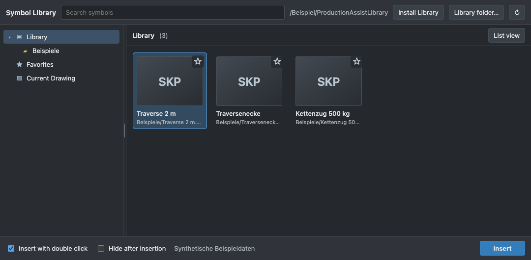
Original HTML dialog from the SketchUp extension, rendered with synthetic library entries.
If needed, choose the library folder using Library folder…, search for a component, and click Insert or double-click the entry if the double-click option is enabled. Then place the component in the model. R switches to alignment by insertion point and rotation direction, M toggles magnetic snapping, and Esc ends insertion. Magnetic snapping requires matching PA magnets on the component and target. The full procedure is described in Library and insertion tool.
SketchUp supports inserting GDTF fixtures. This lets you use device definitions more directly in model planning without creating their geometry entirely by hand. It makes it easier to build a lighting plan from existing fixture resources. The exchange process is described in the MVR and GDTF workflow.
Setup and model import are described in Production Assist for Vectorworks.
Vectorworks supports copying and moving by a specified offset. This lets you place repeated objects evenly without determining each position individually. It speeds up regular arrangements in the rigging plan. The procedure is described in Copy and move native objects.
The results display supports utilization values along the calculated deformation. This lets you view the deformed shape and stress together in the Vectorworks model. This makes it easier to locate results in space. To display a straight shape, you can turn off display deformation in the renderer settings.
The tool for side arms (Side Arms) has been improved. It makes it easier to prepare these attachments in the spatial context of the existing structure. This reduces rework when modeling components arranged to the side. Check the recognized structure and connection after importing it into Production Assist.
Error labels support multiple lines of text. This makes longer notices easier to read on the affected object instead of cluttering the view as one long line. It supports step-by-step model corrections and switching between the message and the component.
The integration supports Layher objects from the RosaProd plug-ins. This lets you transfer corresponding scaffold plans more directly into the Production Assist workflow instead of recreating all the required components. Check the recognized bars and connections. The procedure is described in Import parametric Layher objects.
Objects from the Smart Bridle plug-ins are supported. This lets you include existing suspension assemblies in further planning without redrawing them just for import. This makes it easier to compare the CAD model with the calculation. Requirements are described in Import Smart Bridle.
Speaker and speaker array processing in Vectorworks has been improved. This makes it more reliable to include these systems in the Production Assist model. It reduces rework when comparing an audio plan. Continue to check the imported weights, positions, and attachment points.
The 3D geometry of point and line loads is displayed correctly in Production Assist. The previous display issue no longer makes it harder to locate these load objects in space. This makes it easier to compare the Vectorworks drawing with the imported model. See Geometry of point and line loads.
Connection handling between Vectorworks and the Production Assist app has been improved. This reduces interruptions when switching between the web palette, desktop app, and drawing editing. Ongoing synchronization is more reliable. Information about the two interfaces is available under Web palette and desktop app.
An issue when importing 3D geometry from nested Vectorworks groups has been fixed. This content is no longer lost during import because of this issue. This makes it easier to reuse structured existing drawings without having to ungroup them just for import.
Insert, Select, Patch, and Connect now have their own tools. This lets you switch directly to the task you need instead of first looking for the right function in a combined tool.
| Original icon | Tool | Task |
|---|---|---|
 | PA Insert Tool | Insert Production Assist resources. |
 | PA Select Tool | Select objects using the selection modes. |
 | PA Patch Tool | Run the patch workflow. |
 | PA Connection Tool | Create connections between structures. |
Available modes and requirements are described in Production Assist for Vectorworks.
Installation through the app supports localized Vectorworks editions, such as French and Dutch. This also makes it possible to use suitable installation targets with language variants. This reduces manual setup work. Installation explains the requirements and installation steps.
A Structural Member no longer needs to be recreated as a separate PA component with cross-section values entered by hand. When synchronization is active, Production Assist imports the component and determines static cross-section data from the closed 2D profile. This includes area, centroid, and area moments of inertia; self-weight is also assigned based on the material and geometry. Changes to the profile and component geometry can therefore be accounted for in the subsequent calculation model.
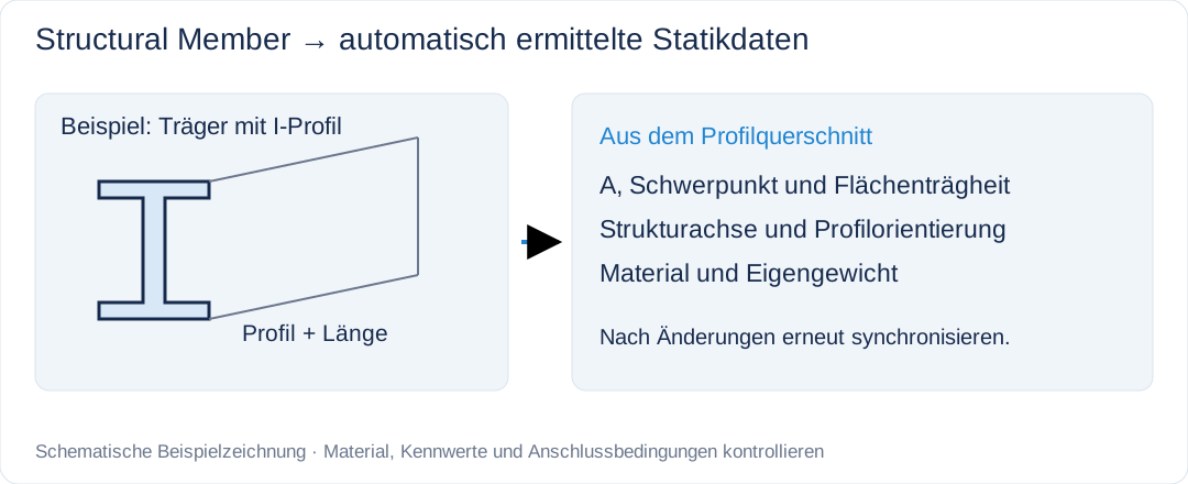
Schematic example: the values are derived from the profile geometry and do not need to be copied individually.
After synchronization, check the profile orientation, length, material, and connections. An unrecognized or missing material may be replaced with S235, so check the mapping actually used. Without an evaluable closed profile, reliable cross-section data is not available. Load-bearing components explains other supported objects.
The redesigned icons also distinguish connection modes more clearly. For example, you can identify rope, drop, pipe, and the number of bridle legs from the tool display. This makes it easier to switch between modeling steps.
| Original icon | Connection mode |
|---|---|
 | Rope |
 | Truss Cross |
 | Drop |
 | Pipe |
 | Bridle with two legs |
 | Bridle with three legs |
 | Bridle with four legs |
Original tool and mode icons from the Vectorworks resources; they do not certify connections or load capacity.
The Production Assist Library is provided as a separate download. This allows the app and library content to be obtained and set up separately. It makes it easier to prepare a workstation for a specific purpose and maintain existing content. When installing for the first time, check whether the required library has already been set up. See Production Assist Library.
The following additions expand the available cross-section data. In each case, select the profile actually in use; a similar name alone does not establish that the values match. Cross-section templates explains how to manage them.
Additional Giant Truss cross sections expand the resources for compatible truss systems. This lets you use existing data as a starting point instead of creating every profile from scratch. It shortens model preparation. Match the manufacturer, specific version, and basis of verification to the component being used.
The X4K-40H cross section adds another available profile. This lets you assign a matching model directly instead of using a different cross section as a substitute or entering all the values from scratch. This simplifies preparing and calculating the corresponding truss lines.
Nova Lite is available as another cross section. This allows compatible truss systems to be prepared using the supplied profile data. It reduces manual data entry and makes consistent assignment within the project easier. Check the data against the specific version actually in use.
The documentation has been revised to explain the controls and how to use them in more detail. This makes it easier to look up functions independently instead of working out how to use them by trial and error. It helps users get started and resolve common questions during planning. Start with Production Assist or the user interface.