

Open the Resource Manager from Window → Resource Manager. The tabs at the top switch between resources and templates:
Available actions depend on the active tab and on whether you are editing a drawing resource or a template. The Resource Manager also shows a preview or tabular properties when the relevant tab provides them.
| Field / Area | Description |
|---|---|
| Tab bar | Switches between the resources and templates listed above. |
| Content area | Shows the list or editor for the currently selected tab. |
The administration page for shared resources is a separate area, not a tab in the Resource Manager. It manages shared resources and categories and is available only with the required permissions. Uploading resources to the cloud is described in the Labels & Background section and under Upload or update a resource from the Resource Manager. The separate DWG Library Manager is used to check and import DWG truss folders. It is not the same as the DWG Browser for AutoCAD.
The standalone DWG Library Manager checks DWG truss folders, assigns Production Assist cross sections, and imports finished files into the AutoCAD library. Its guide explains the complete workflow and distinguishes the manager from the DWG Browser in the AutoCAD plugin.
The Meshes tab contains the 3D geometry in the current drawing, including meshes used in symbol definitions or fixture types. Select a row to see a preview and the bounding dimensions along the X, Y, and Z axes on the right.
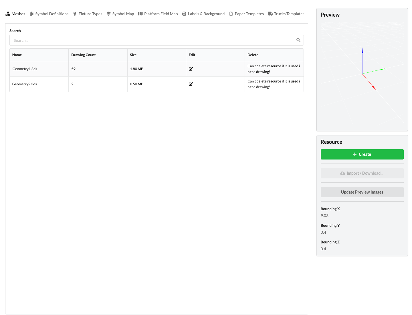
The table shows the name, Drawing Count, mesh size, and available actions. Drawing Count indicates how many times the mesh is used in the drawing. A mesh with a Drawing Count greater than zero cannot be deleted.
Click Create on the right to import a mesh file into the drawing. The file dialog supports .3ds, .fbx, .gltf, .glb, .obj, .stl, and .dae. Refresh Previews regenerates the mesh previews. Import / Download... is disabled in the Meshes tab; import meshes from other sources through the resource selector at the relevant insertion point.
Click Edit to open the geometry in Edit Mode. You can delete a mesh only when its Drawing Count is 0. If the geometry is in use, first remove all objects that use the mesh.
The Symbol Definitions tab lists the symbols in the current drawing. A symbol definition can contain geometry and other content, such as electrical connections, structural elements, or support elements. Select a row to display its preview and associated properties.
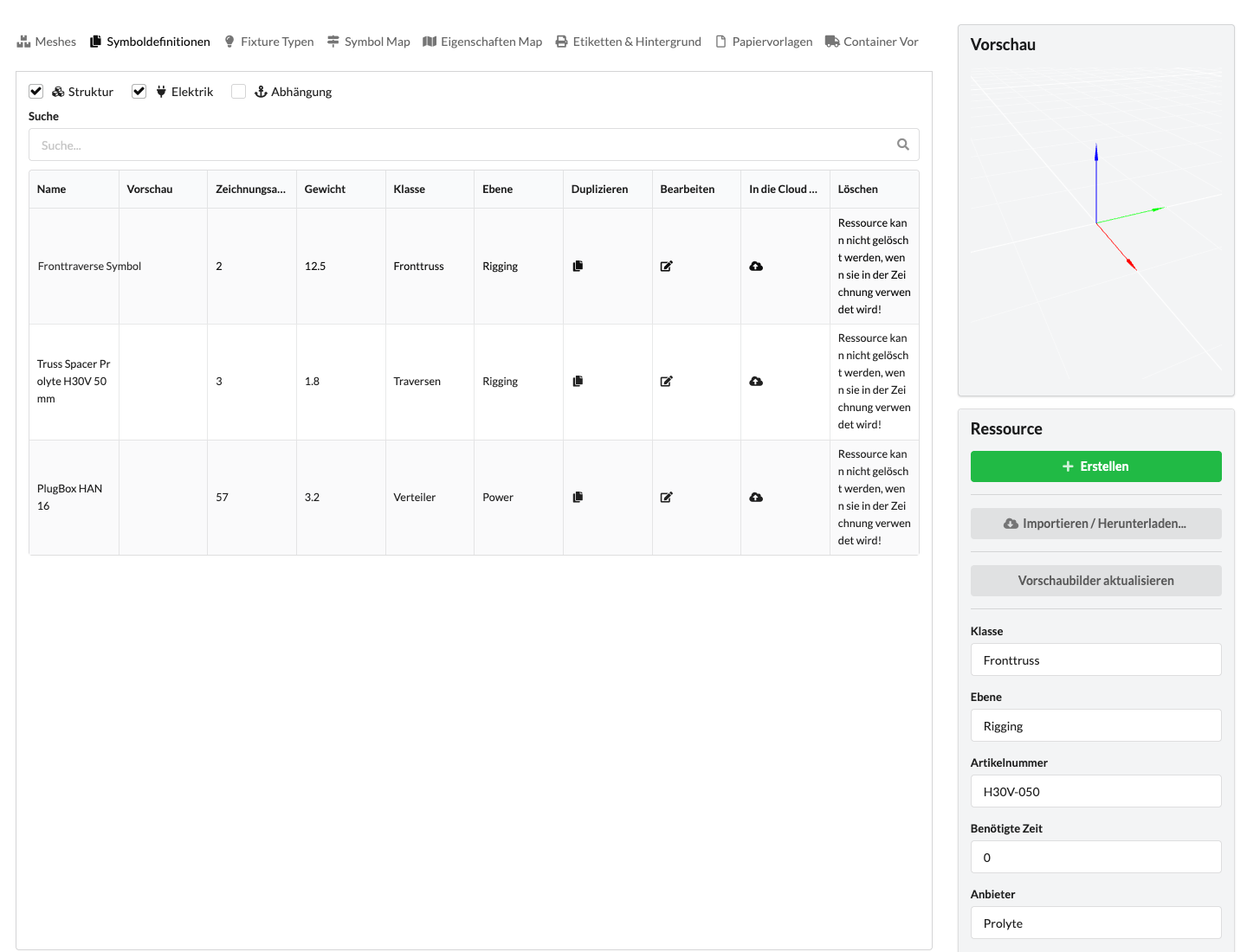
The table shows the name, preview, Drawing Count, and actions. Use the name search to find entries. Structure shows symbol definitions with structural elements, Electrical shows those with a Wiring object, and Rigging shows those with a Support element. When multiple filters are enabled, the list shows entries that match at least one of them. The properties on the right include the class, layer, item number, required time, supplier, and weight.
See the Symbol Workflow for more steps on building a symbol definition.
Use Duplicate to create a copy of a symbol definition. A symbol definition with a Drawing Count greater than zero cannot be deleted. First remove the objects that use it; then you can delete the unused entry. You can upload your own symbol definitions using the cloud icon in the row; this requires a signed-in account and an internet connection.
The Fixture Types tab lists device definitions in the current drawing, including imported GDTF files and types of fixtures that have already been placed. A fixture type describes the device; importing it does not place a fixture in the plan. To place one, select Toolbar New Object → GDTF, choose the type under Current Drawing, and place the fixture in the renderer.
The table shows the name and Drawing Count. Select a row to see a 3D preview of the fixture type on the right. A Drawing Count greater than zero means that fixtures in the drawing use the type; such entries cannot be deleted.
You can upload your own fixture types using the cloud icon in the table row; this requires a signed-in account and an internet connection. You can delete a fixture type only when its Drawing Count is 0. First remove all fixtures that use the type. For more information about importing and placing fixtures, see the GDTF and MVR Workflow.
The Symbol Map assigns incoming symbol names to matching Production Assist symbols. These mappings are used when importing MVR files and supported Vectorworks symbols and AutoCAD blocks. In the Resource Manager, you can add, edit, copy, or delete mappings.
In the Symbol Map tab, you can see existing mappings between incoming symbol names and Production Assist symbols. Click the red delete icon to remove a mapping. Click the pencil icon to edit it, or the copy icon to copy its details into a new entry.
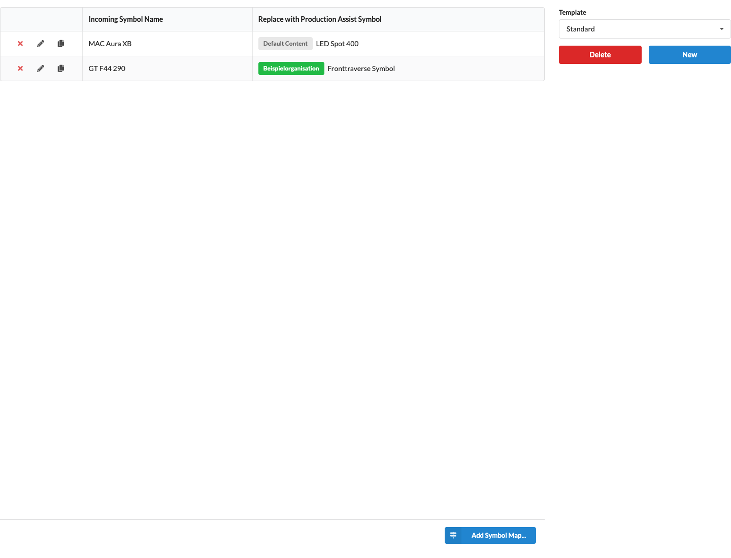
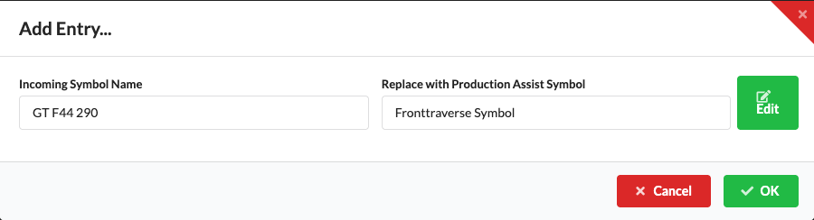
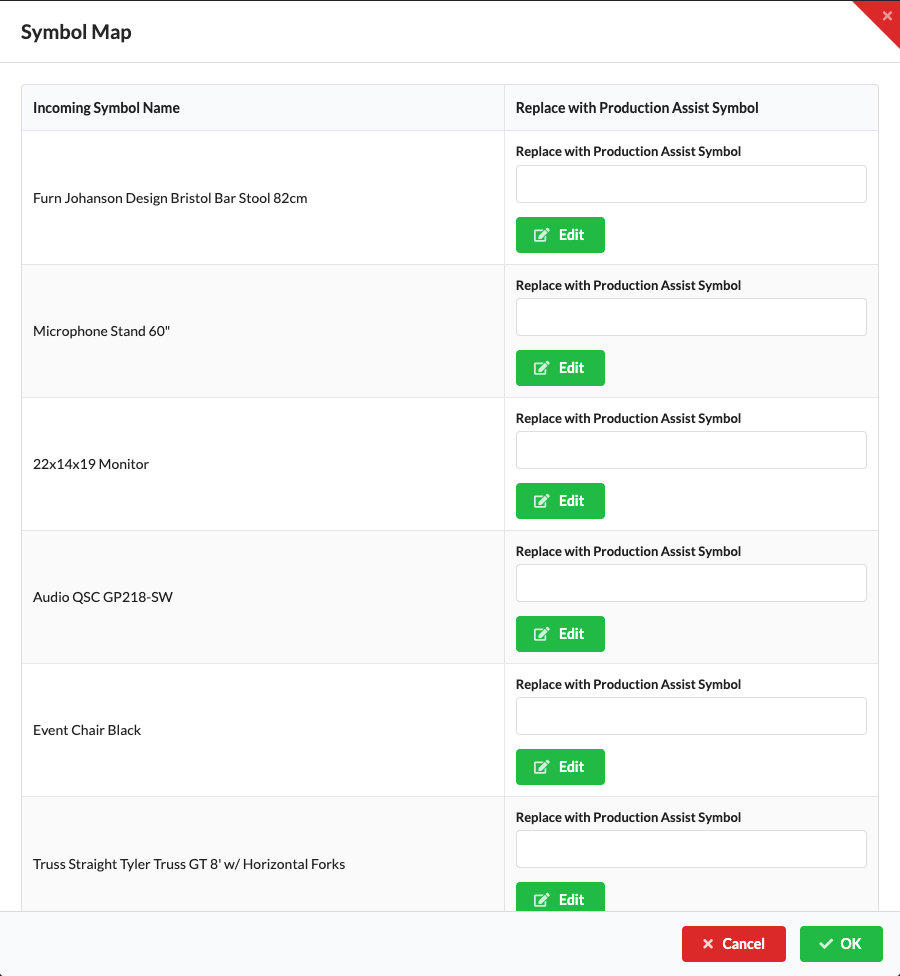
| Field | Description |
|---|---|
| Incoming Symbol Name | Name under which a symbol or block appears in the import source. For each entry, you can choose a matching target symbol under Replace with Production Assist Symbol. |
| Replace with Production Assist Symbol | Target symbol for the import. |
| Import Groups | Enabled by default during MVR import. Groups in the MVR file are created as assembly groups (Assembly Groups). If unchecked, their contained objects are imported without these groups. |
When you import an MVR file containing symbols, a row appears for each entry. Click Edit in that row to select the replacement symbol from Online Drawing or User Resources. An internet connection is required to use an online symbol that is not yet available locally. OK saves the selected mappings and starts the MVR import; Cancel closes the dialog without starting the import. The mappings apply to future MVR imports and do not replace objects that have already been imported. Import Groups is enabled by default: groups in the MVR file are then created as assembly groups. If you disable it, Production Assist imports the contained objects without these groups. For detailed instructions, see the MVR import workflow.
If the drawing is not linked to an online project, you can select a Symbol Map template under Template on the right. Click New to create a template or Delete to remove the selected one. Mappings that you edit afterward belong to the selected template. For a drawing linked to an online project, the right side instead shows Template and Update, which let you apply mappings from a template to the project.
Templates are useful when you import MVR files from different customers whose symbols need different mappings. New creates a template, and Delete removes the selected template.
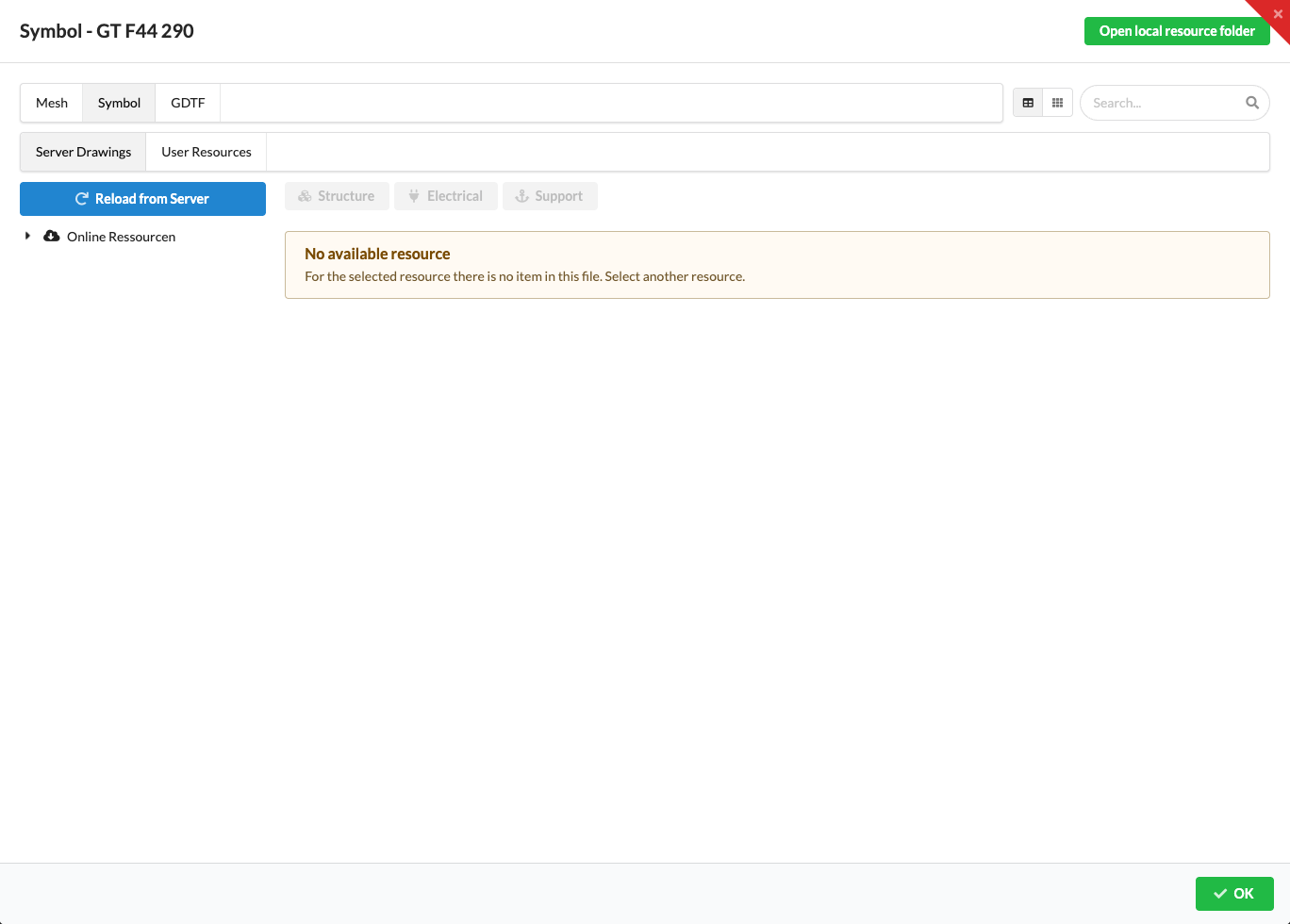
| Field / Control | Description |
|---|---|
| Online Drawing / User Resources | Selects the source for the replacement symbol. The current drawing and local resources are not available in this selector. |
| Search and resource list | Searches for a Production Assist symbol and adds it to the mapping when selected. |
On the Property Map tab, you link fields from a host application to Production Assist properties. This applies to supported plug-ins such as Vectorworks and to block attributes in AutoCAD or BricsCAD. For CAD blocks, select AUTOCAD_BLOCK as the platform object name.
When Use Unit is disabled, Production Assist multiplies a numeric value it reads by the factor; when writing the value back, it divides the internal value by the factor. For a CAD weight attribute in kilograms without a unit string and an internal weight in grams, use 1000. More CAD examples are in the guides for AutoCAD and BricsCAD.
The current tab and the dialog for adding a mapping show both the host fields and the Use Unit switch.
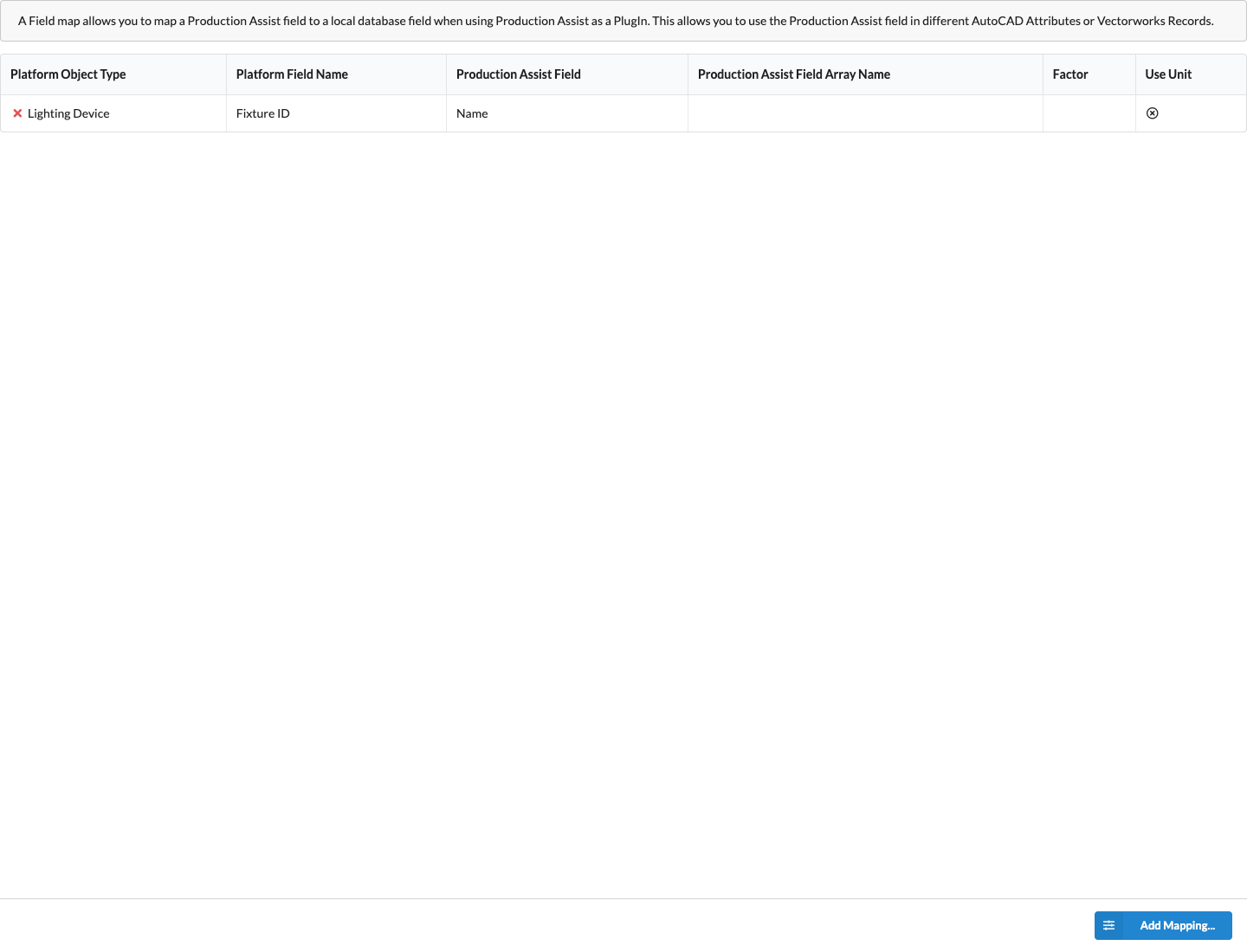
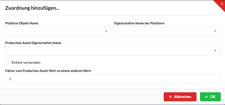
| Field | Description |
|---|---|
| Platform Object Name | Host object type; for CAD blocks, AUTOCAD_BLOCK. |
| Platform Property Name | Field name in the host record or CAD block attribute name. |
| Production Assist Property Name | The mapped property in Production Assist. |
| Production Assist Property Array Name | The array, if the selected property is part of a repeatable property group. |
| Use Unit | Uses the unit of the selected property or attribute value; disables the factor. |
| Factor | Converts numeric values without units: CAD or host value × factor when read; internal value ÷ factor when written back. |
In the Resource Manager, manage label templates and templates for label and report backgrounds under Labels & Backgrounds. Select a template in the list to see its preview on the right.
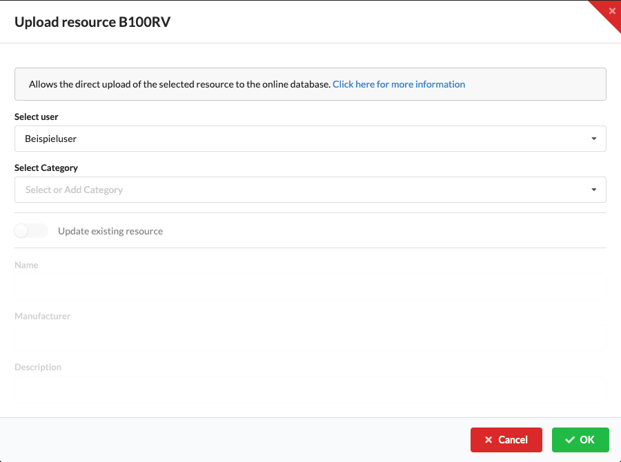
The online resource is saved under the selected user and in the selected category. For more information about shared resources, see Uploading or updating a resource from the Resource Manager.
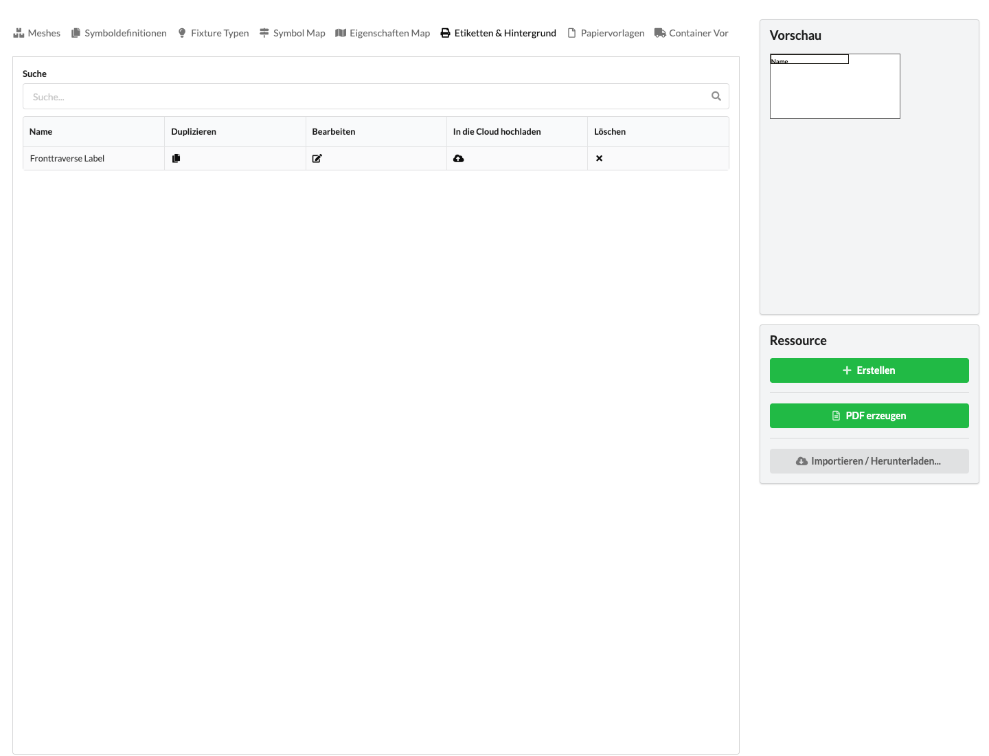
The guide to creating and printing labels describes label types, paper sizes, fields, and PDF export in detail. The backgrounds tutorial explains how to use a label template as a report background.
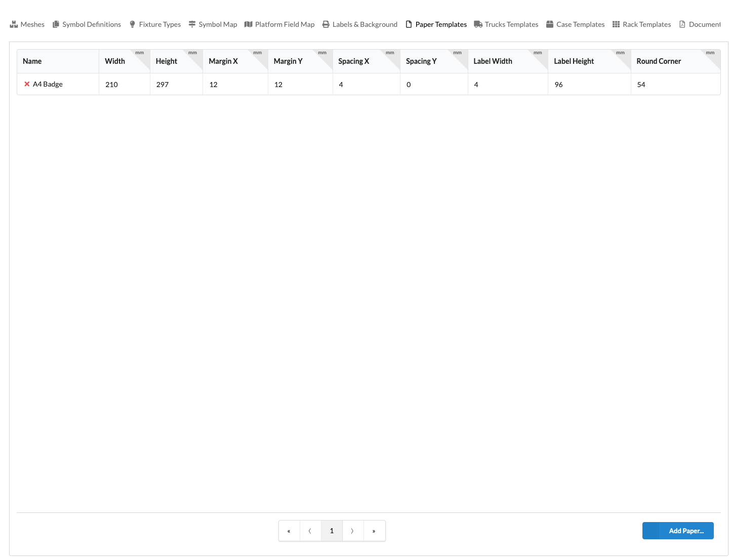
Use the Paper Templates tab to manage reusable paper and label dimensions for PDF export. The list shows existing templates. Edit values directly in the table cells; the change is saved when you leave the field and applied to label templates that use this paper template. Click the red X in front of a name to delete a template.
Select Add Template... to create a new paper template. The Edit Paper Template dialog contains a name field as well as fields for paper, margins, label spacing, and label dimensions. The name field is prefilled with New Paper Template when the dialog opens; however, the interface does not require a non-empty name. The dimensions start at 0 and cannot be negative. OK creates the template and closes the dialog. Cancel, the close icon, clicking outside the dialog, or pressing Esc closes it without creating the template. Enter confirms in the same way as OK.
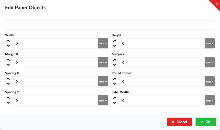
Enter the dimensions in the displayed units. OK saves the new template; Cancel discards it.
| Field | Description |
|---|---|
| Width / Height | Dimensions of the paper format. |
| Margin X / Margin Y | Set the horizontal and vertical page margins separately. |
| Spacing X / Spacing Y | Set the horizontal and vertical spacing between labels. |
| Label Width / Label Height | Dimensions of a label. |
| Rounded | The current Resource Manager displays this field but does not save changed values for it. Set rounding directly in the label template. |
If you need different values for Margin X and Margin Y, edit both table fields in the Resource Manager. The Create and Update actions in Object Properties → Print Label currently save Margin Y with the value of Margin X. Changes to a template are applied to linked label templates; any custom paper dimensions or margins on such a label are replaced with the template values.
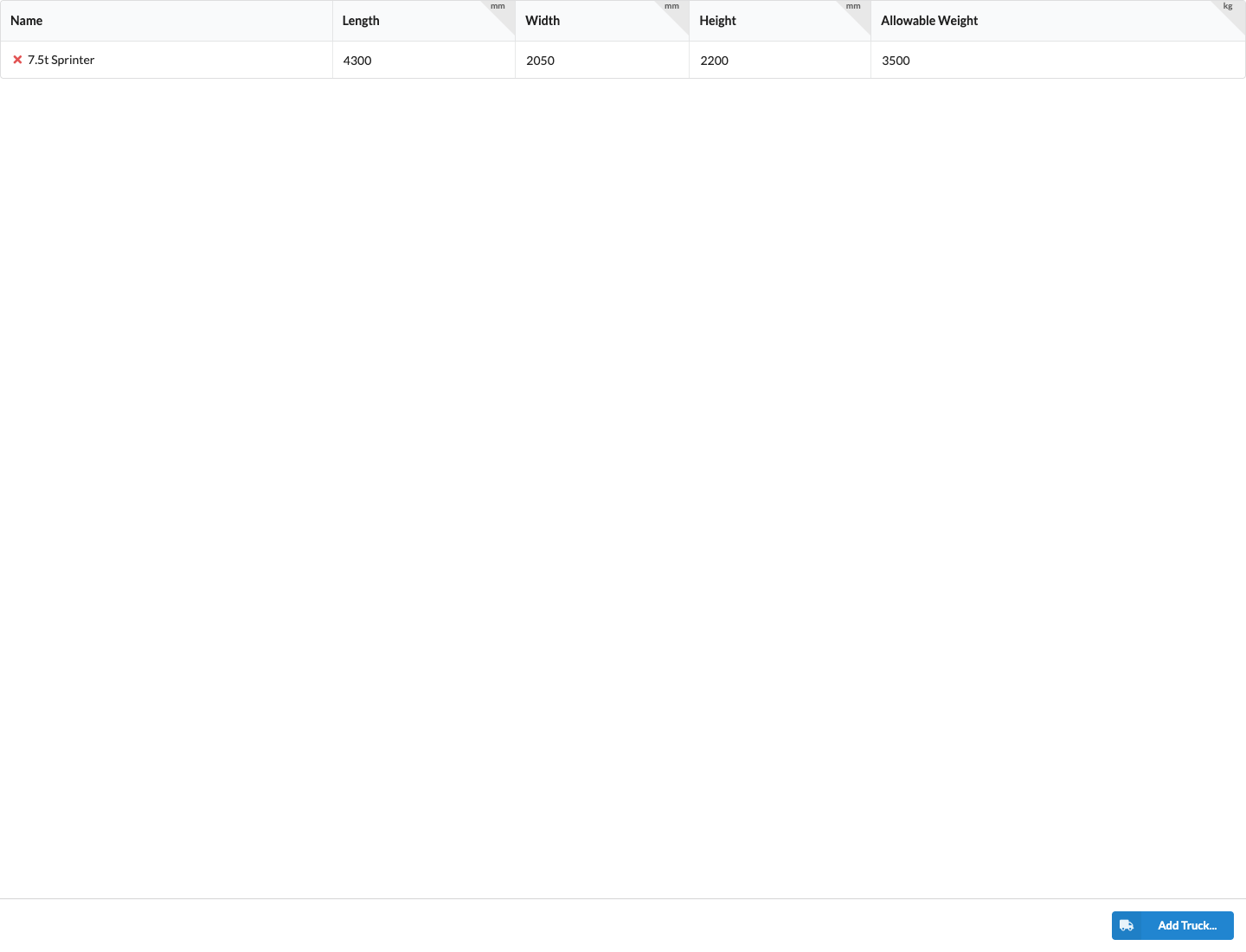
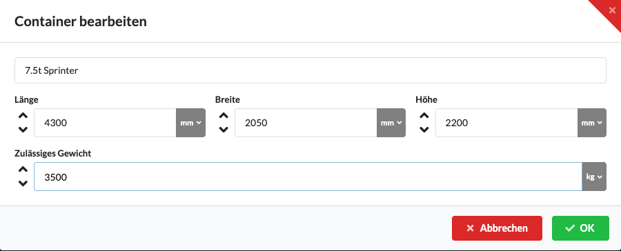
Use the Resource Manager’s Container Templates tab to create reusable truck templates. You can then create the trucks needed for the drawing from a template in the Containers Navigation tab. Existing templates are listed with their dimensions and allowable load weight. Click the red X in front of a name to delete a template.
| Field | Description |
|---|---|
| Name | Name of the truck template. |
| Length / Width / Height | Interior dimensions of the template; the current input form labels them Length, Width, and Height. |
| Allowable Weight | Allowable payload in the displayed weight unit. |
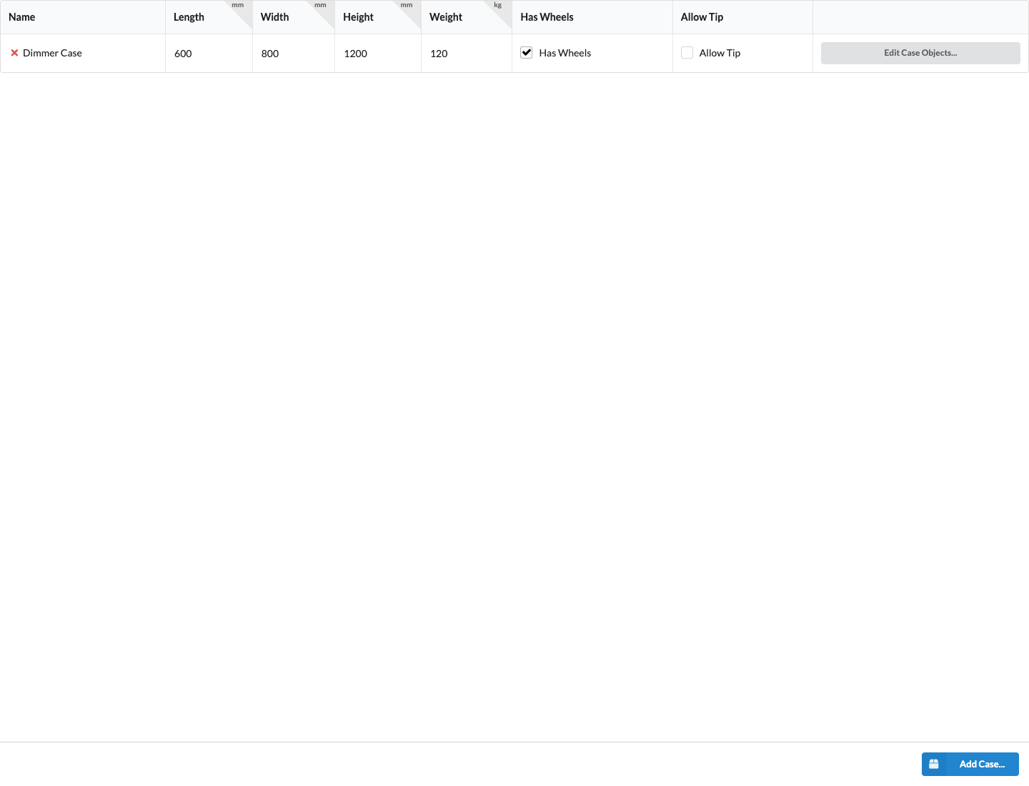
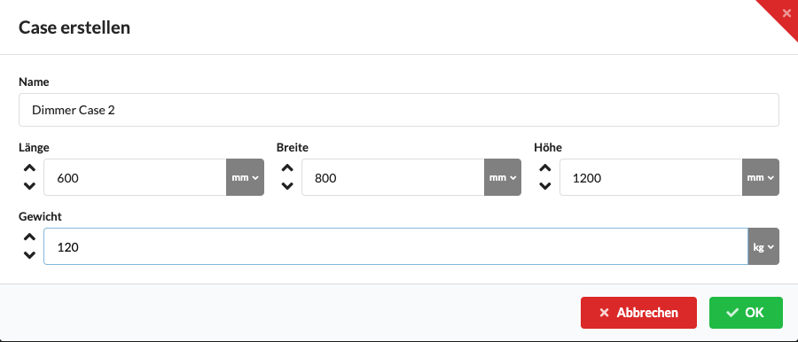
Use the Case Templates tab to create reusable cases with outer dimensions and tare weight. You can then create cases for your drawing in Cases in Navigation. The table shows saved templates. You can edit dimensions, weight, and the Has Wheels and Tippable? options directly in the row; the change is saved when you confirm the field. Click the red delete icon to remove a template.
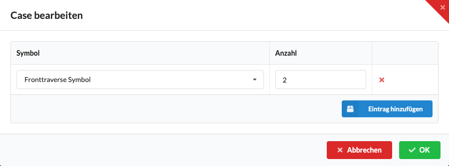
Select Edit Case... in a template row to open the Edit Case dialog. The table shows the included symbols and their Quantity. Select Add Entry to choose a symbol from the available resource list. Production Assist saves additions, symbol selections, and removals immediately; a changed quantity is saved when you leave the field. OK and Cancel close the dialog; Cancel does not undo changes already saved. This defines the intended contents of the template; to pack a specific case, use cases in Navigation.
| Field | Description |
|---|---|
| Name | Name of the case template. |
| Length / Width / Height | Outer dimensions of the case. |
| Weight | Tare weight of the case. |
| Has Wheels / Tippable? | Indicates whether the case has wheels and can be tilted in the truck. |
| Edit Case... | Opens the template’s symbol and quantity list. |
In the Rack Templates tab, you can create reusable rack sizes with their dimensions, height units, and tare weight. You can then create the racks for your drawing in Racks in Navigation. The table shows the saved templates. Select Add Rack to create a template. Select Edit Rack Template to change its dimensions, weight, height units, and the Has Wheels and Tippable? options. Select the red delete icon to remove a template.
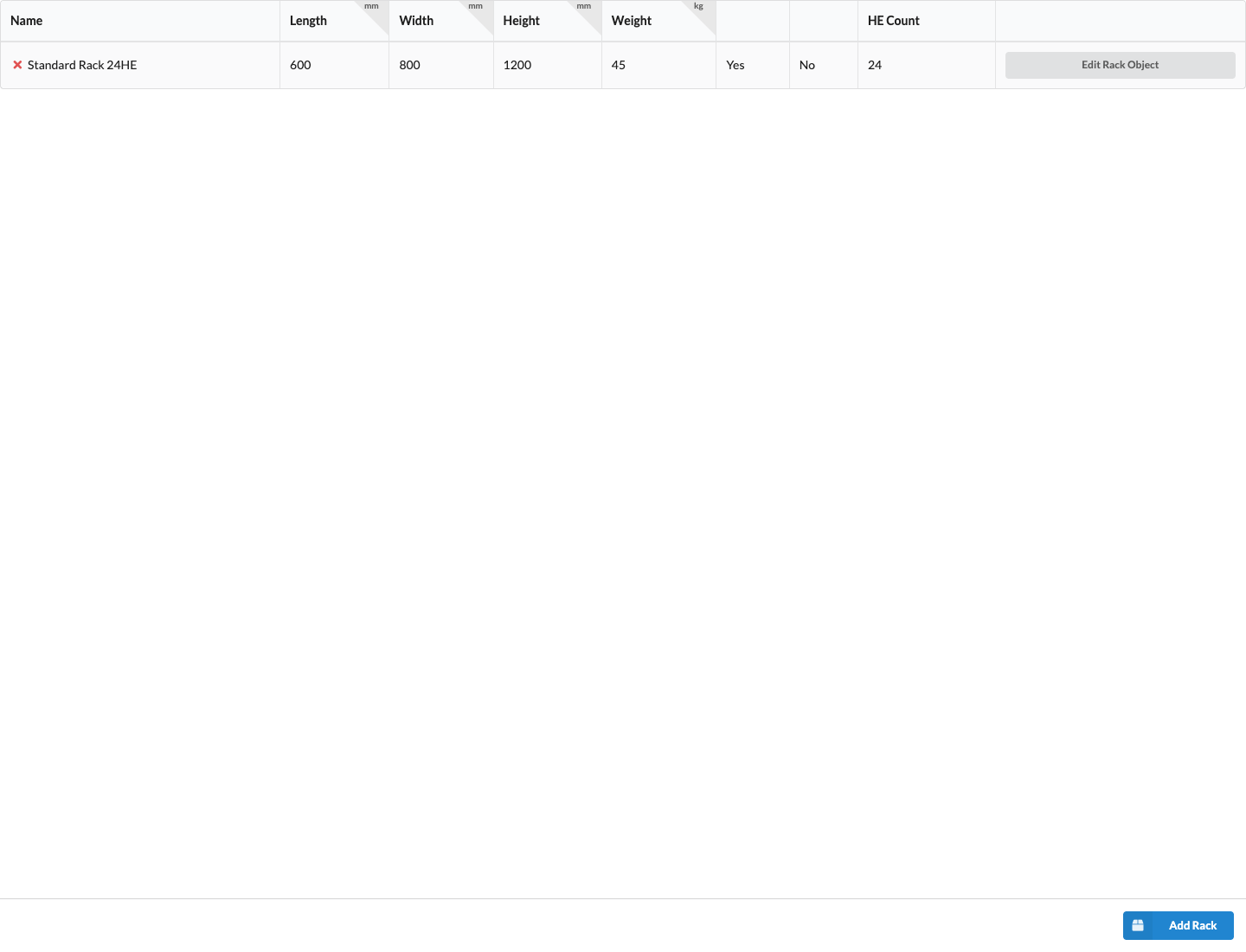
Select Add Rack to open the Create Rack Template dialog. Enter a Name, Length, Width, Height, Weight, and HE Count. The numeric fields start at 0; length, weight, and HE values cannot be negative. Select Has Wheels if the rack has wheels, and Tippable? if it may be tilted in the truck. These properties are available for truck planning. Select OK to create the template, or Cancel to close the dialog without making changes.
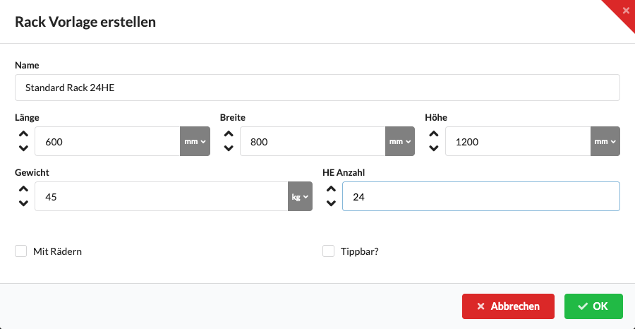
| Field | Description |
|---|---|
| Name | Name of the rack template. |
| Length / Width / Height | Outer dimensions of the rack template. |
| HE Count | Height units of the rack. |
| Tare Weight | Weight of the empty rack. |
| Has Wheels / Tippable | Indicates whether the rack has wheels and may be tilted in the truck. |
In the Documents tab, you can store documents such as inspection reports. Select Add Document... to import a document. Then select Open to display a PDF file in Production Assist, or Delete to remove it from the list. The preview cannot open files larger than 1.5 MB.
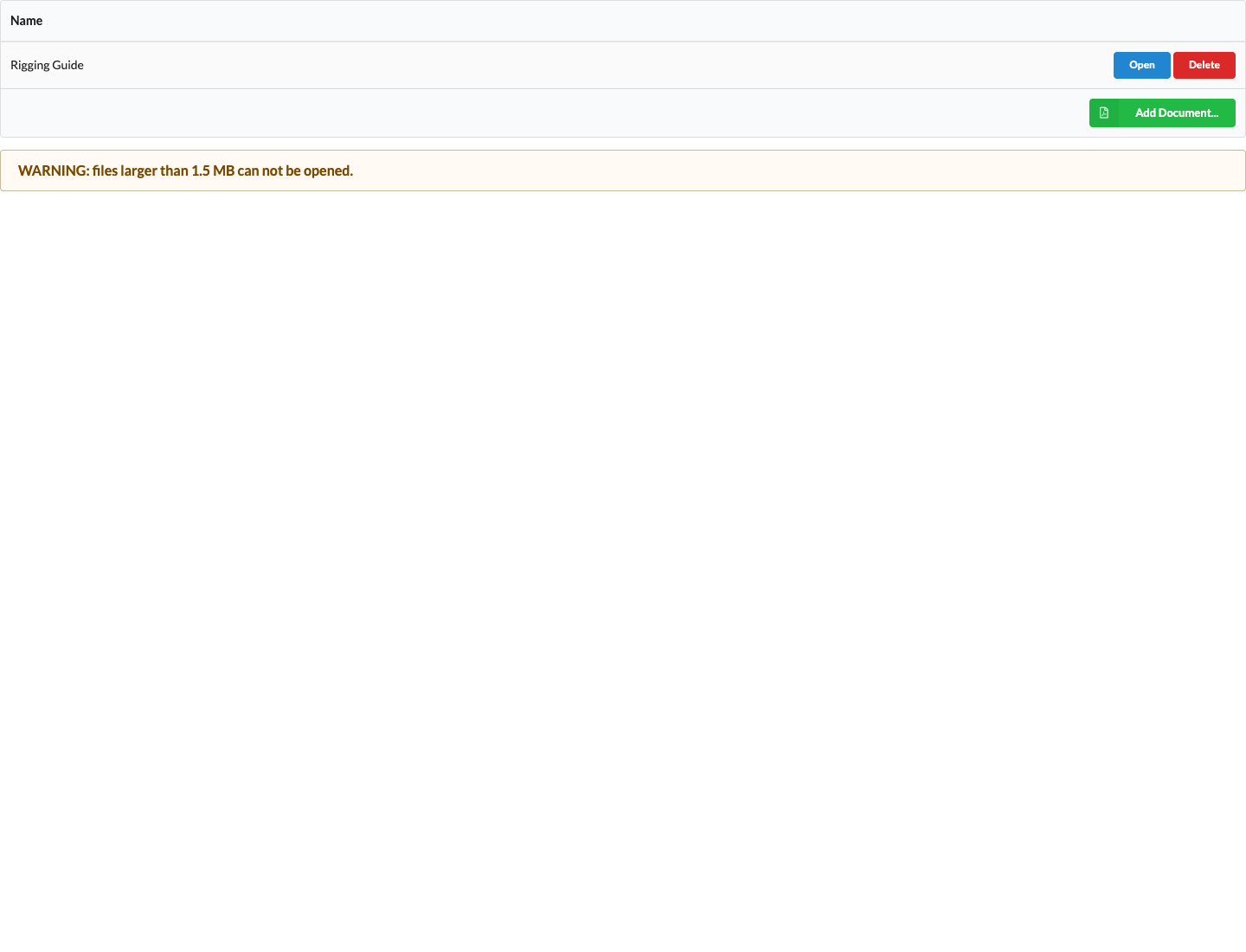
The PDF preview dialog uses the name of the open document as its title and displays its PDF content. Select Cancel, the close icon, click outside the dialog, or press Esc to return to the list. The dialog displays OK, but it currently has no associated action.
| Field / control | Description |
|---|---|
| Name | Shows the name of the imported document. |
| Open | Displays the PDF file in a dialog. Files larger than 1.5 MB cannot be opened in this preview. |
| Delete | Removes the document from the list. |
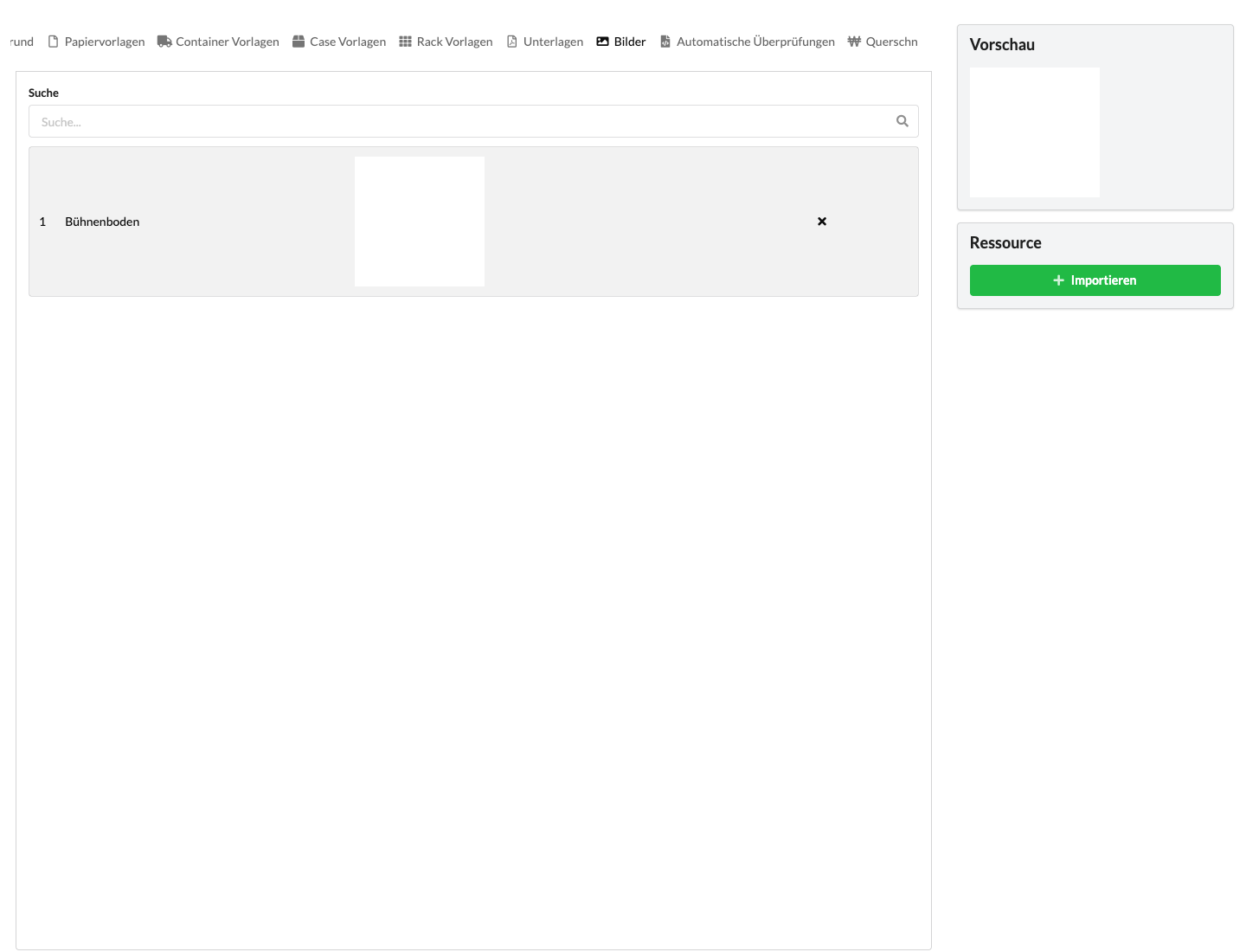
The Pictures tab shows available preview textures and images that have already been imported into the drawing. Use the search field to filter both lists by name. Select an item to see its preview and the Import action on the right. Import opens the file picker for an image file (.png, .svg, or .jpg); it does not import the selected list item. If you close the file picker without selecting a file, nothing is imported. You can remove images that have already been imported from the drawing using the delete icon in their row.
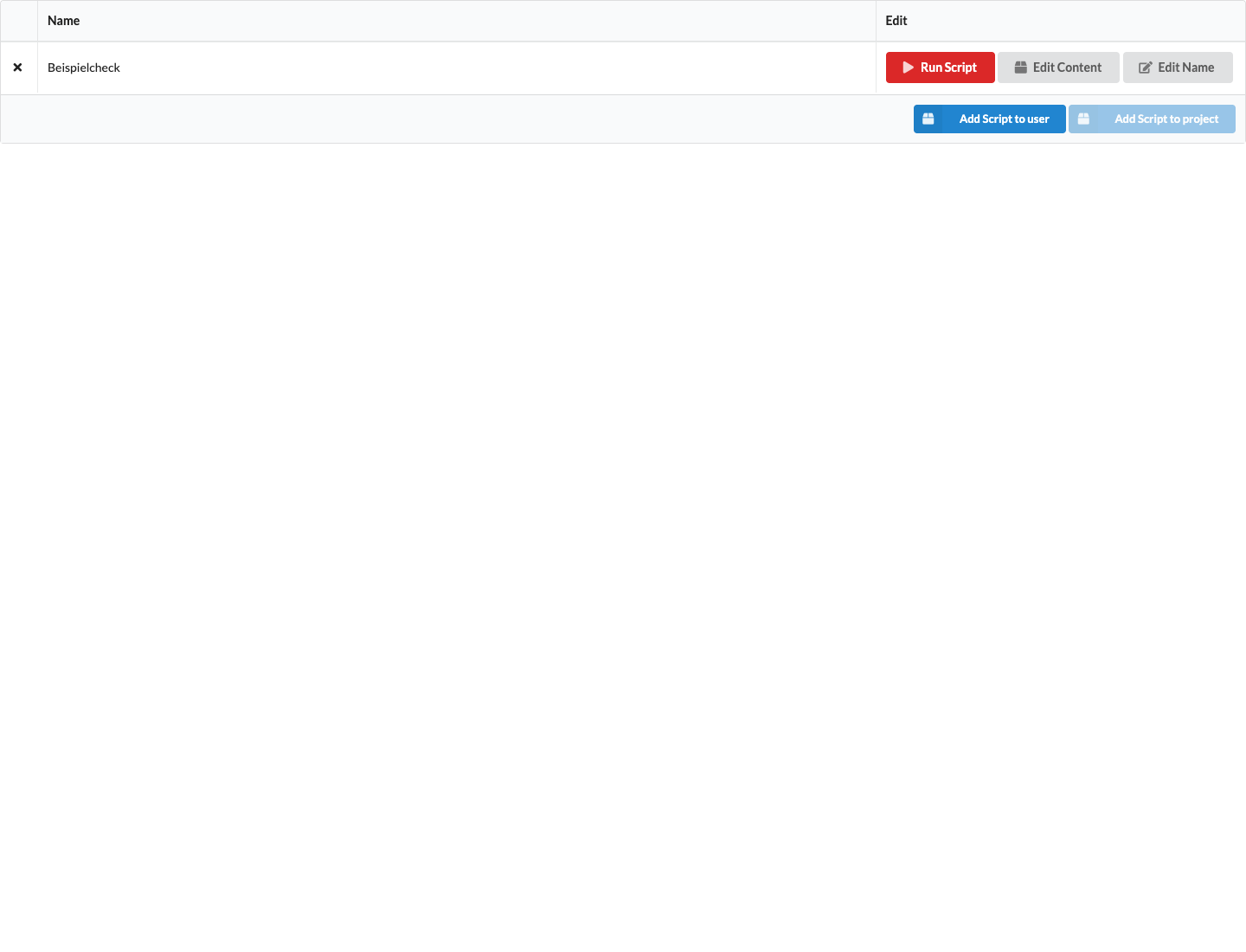
The Automatic Checks tab shows your checks. If no online project is linked, user-specific checks are shown. In a linked project, you can find project checks and checks belonging to the project owner, which you can enable for the project. The status of server checks appears in the change request.
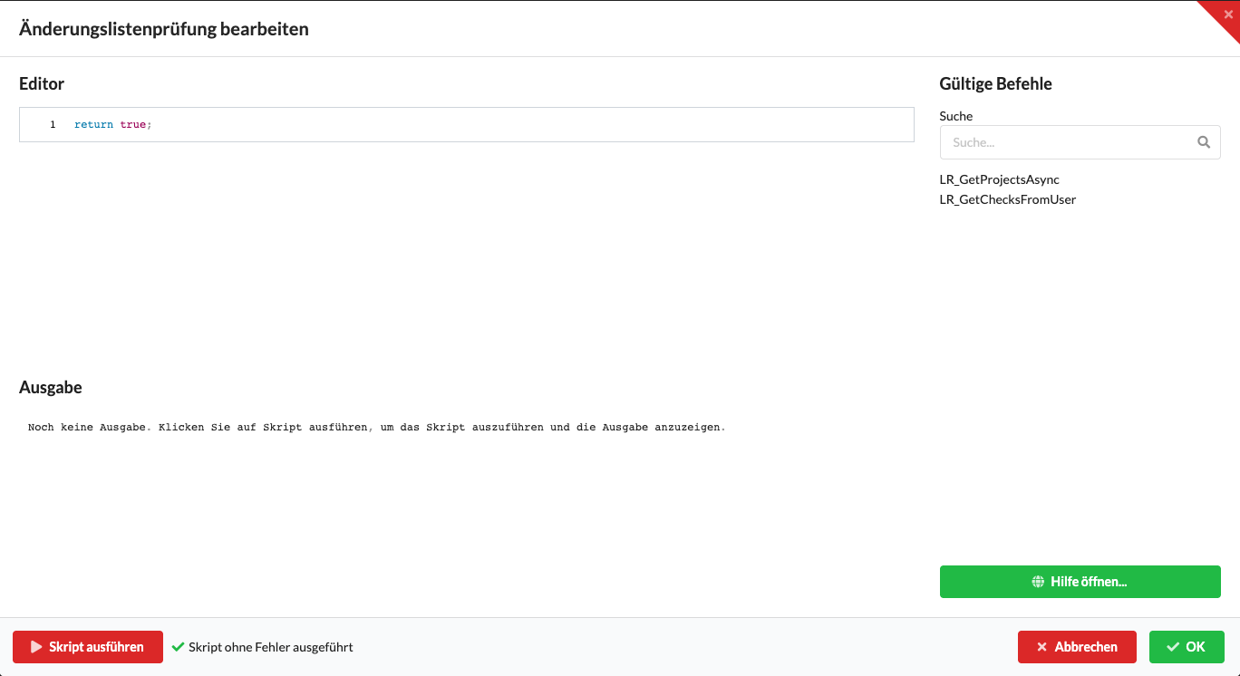
Select Edit Content to open the full-screen Edit Change List Check dialog. Edit JavaScript in the line-numbered editor on the left. On the right, Valid Commands lists the available functions; use the search field to filter the list. The Output area shows the log and result after a run. Run Script runs the current editor content for checking and then shows the success or error status. OK saves the script change. Cancel, the close icon, or a click outside the dialog closes it without saving; Esc does not close it. Select Edit Name to change the name directly in the table row and save it with OK; Cancel discards the name change. Add Script to User adds a user-specific check. Add Script to Project is available only when an online project is linked and adds a project check. You can remove project checks from the list; enable or disable checks belonging to the project owner using the selection box.
For automatic execution on the server, also enable Run Checks on Server under Settings → Access in the online project. See the guide to check scripts for available commands and examples, and the change request workflow for project approvals and error status.
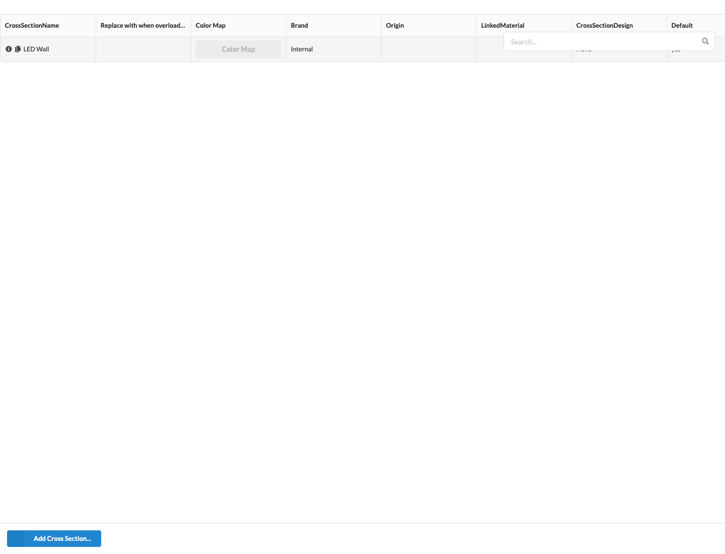
The Cross Section Templates tab lets you manage profiles for structures. Select Create Cross Section... to open the Create Cross Section dialog. In the table, you can search, sort, and edit existing templates; Details opens a read-only property view of the selected template. Use dimensions and material assignments that suit your system and verification.
Like Hinge Start / End, cross section templates can also contain separate connection settings for the start and end. Details displays these as Default values for start connections, Default values for end connections, and Minimum member length for rotational connections. The settings are used automatically as long as the structural geometry or enabled custom hinges on the object do not specify an explicit mode. Replacing a cross section uses the settings of the replacement profile. The connection settings are read-only in this form; edit individual connections under Object Properties → Hinges → Connection Springs…. Custom cross section settings can be stored through the cross section API and are saved with the drawing.
The four O/U-beam profiles K2000+, each with and without Enforced, as well as Layher - Dubbele Spiekop, include matching Layher connection settings. For beams shorter than 600 mm, the rotational components are released. U-beams do not transfer torsion in the setting. The double wedge-head coupler contains two cDK rotational springs and only a portion of the explicitly named vertical slip approximation. These settings do not create replacement-model geometry or perform an additional load-capacity or interaction verification.
In the creation dialog, enter Name, Manufacturer, Origin, material, Cross Section Design, Bracing Design, and Used Verification. The material selector contains the existing material templates. Assign Cable Load and Define Dead Load via Material control how cable and dead loads are applied. Geometric and structural values follow below. When opened, Cross Section Design is set to Undefined, Bracing Design to None, and numeric inputs to 0. OK creates the template or saves an edit; Cancel closes the form without saving its changes. Details shows the available identification, geometry, and load data; OK closes the read-only view.
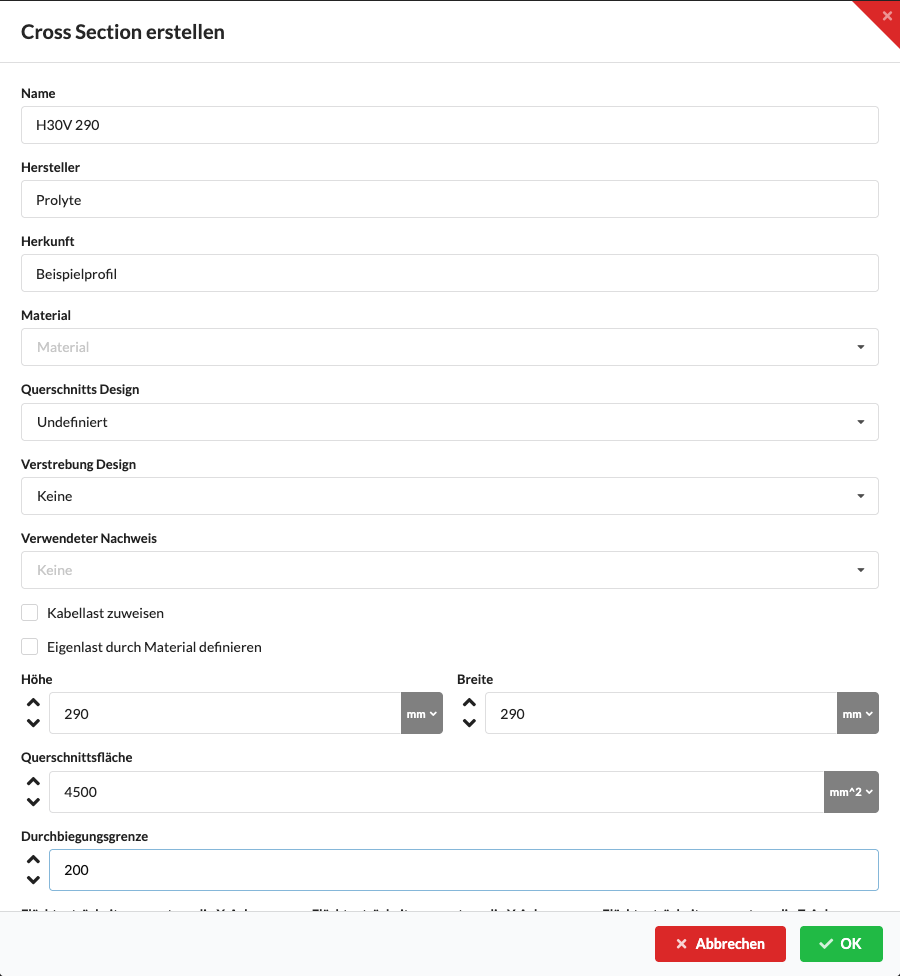
The input fields are grouped by purpose:
| Field group | Description |
|---|---|
| Name, Manufacturer, Origin | Identify the profile and its source. |
| Material, Cross Section Design, Bracing Design, Used Verification | Link a material and define the profile type, bracing pattern, and calculation standard. |
| Height, Width, Cross-Section Area, Deflection Limit | Describe the profile geometry and its deflection limit. |
| Ftm XX, Ftm YY, Ftm ZZ | Record the moments of inertia about the three axes. |
| Nx, Vy, Vz; Mxx, Mby, Mbz; Qx, Qy, Qz | Store the profile's axial, shear, moment, and line-load values. The input fields show their units. |
| Force Chords, Force Connector, Force Bracing Horizontal/Vertical, Chord Diameter | Record additional structural values for chords, connectors, and bracing. |
| Dead Load per Distance | Specifies the dead load per unit length. |
The values in the renderer screenshot are synthetic examples for reference and are not design specifications.
| Field | Description |
|---|---|
| Name | Name of the cross section. |
| Geometry and inertia values | Describe the profile's shape, dimensions, and structural properties. Units are shown in the table columns. |
| Details | Opens the details view for the selected template. |
| Duplicate / Delete | Creates a copy or removes a template. |
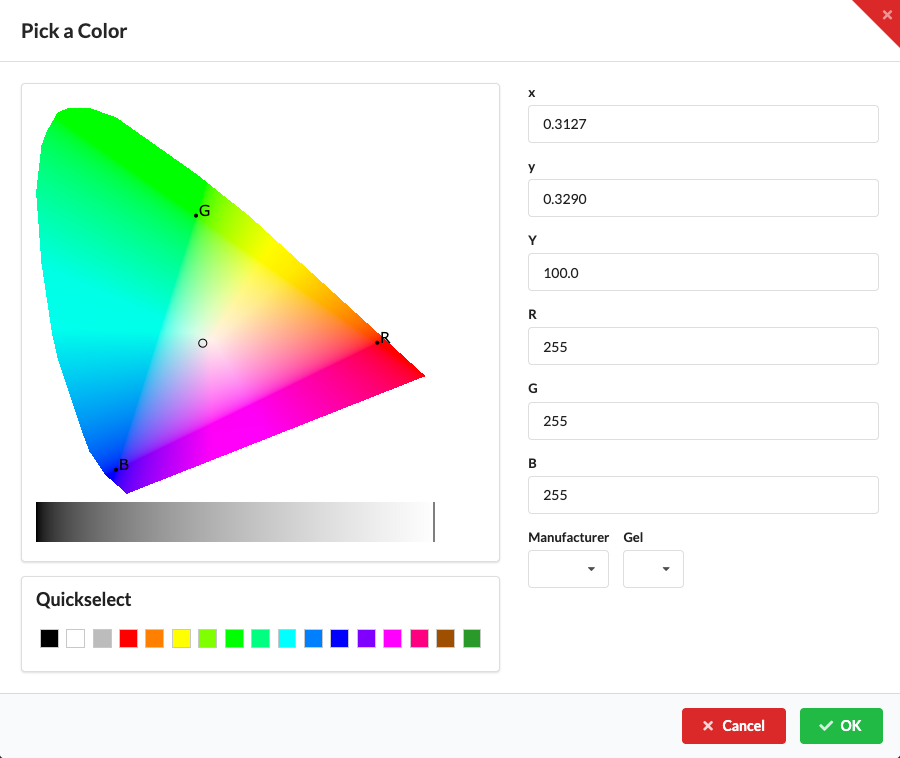
Edit layer colors using the color dot in Layers in Navigation, not in a cross section template. The dialog provides a color field with a brightness gradient, Quickselect, CIE values x, y, and Y, and RGB values. You can also select available color sets using Manufacturer and Color Filter. OK applies the color to the layer; Cancel discards the selection.
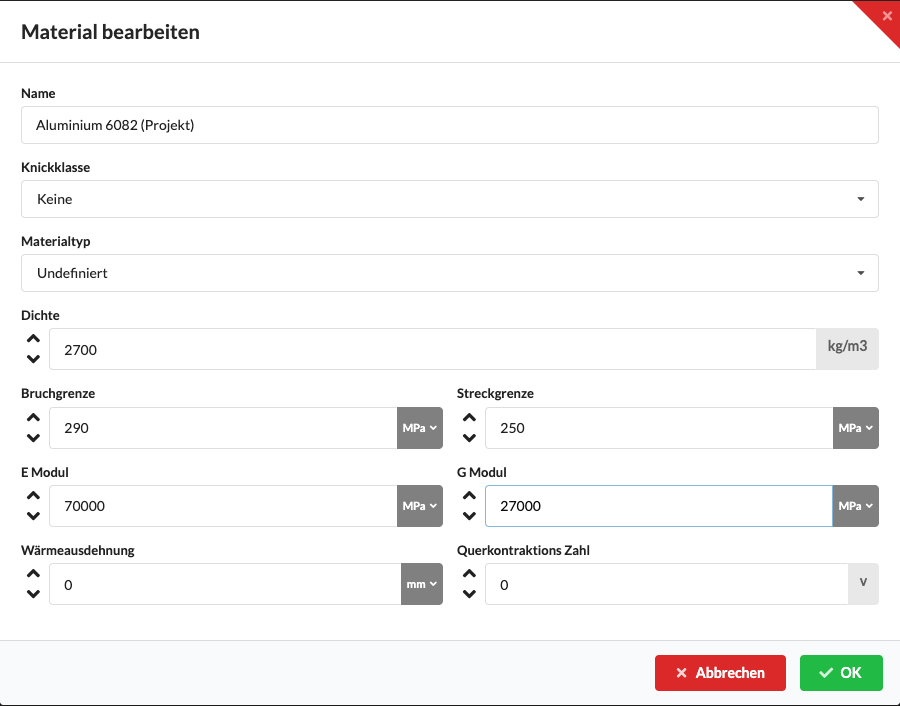
The Material Templates tab lets you manage material properties for calculations. Add Material opens the Edit Material dialog. There, set Name, Buckling Class, Material Type, Density, Tensile Strength, Yield Strength, E Modulus, G Modulus, Thermal Expansion, and Poisson's Ratio. When creating a material, Buckling Class is set to None and Material Type to Undefined. OK saves a new or edited entry; Cancel closes the dialog without applying unsaved form changes. You can sort the table by column and filter it by name using the search field. For custom materials, edit values such as density, elastic and shear modulus, yield strength, and thermal expansion directly in the editable fields. Standard materials cannot be edited or deleted.
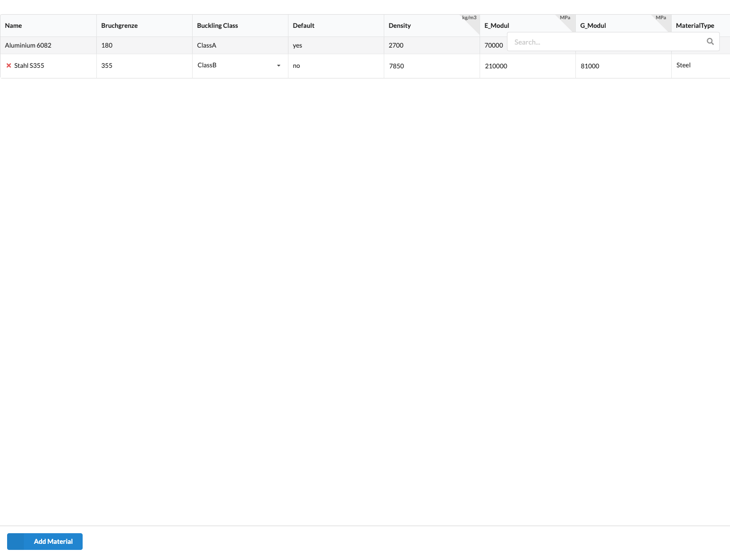
Custom material templates belong to the active drawing's resources and are saved with the drawing. Production Assist loads the default values from default_material.json in the AppData area; if that file is not there, the bundled template is used. The material list is also transferred to the server when online resources are synchronized.
| Field | Description |
|---|---|
| Name | Name of the material. |
| Material Type / Buckling Class | Assigns the material to a type and an available buckling class. |
| Density, E Modulus, G Modulus, Yield Strength, Thermal Expansion, Poisson's Ratio | Material properties; the units are shown in the table. |
| Delete | Removes a custom material. Standard materials are protected. |
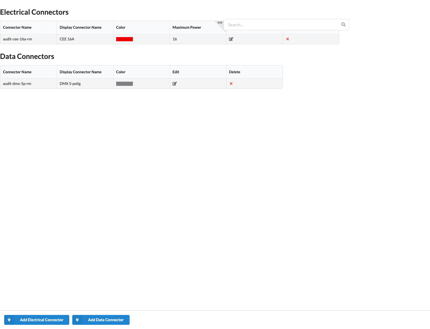
The Connector Templates tab lets you manage electrical and data connectors used by Production Assist in connection and cable plans. A connector can have pins and a list of compatible connectors.
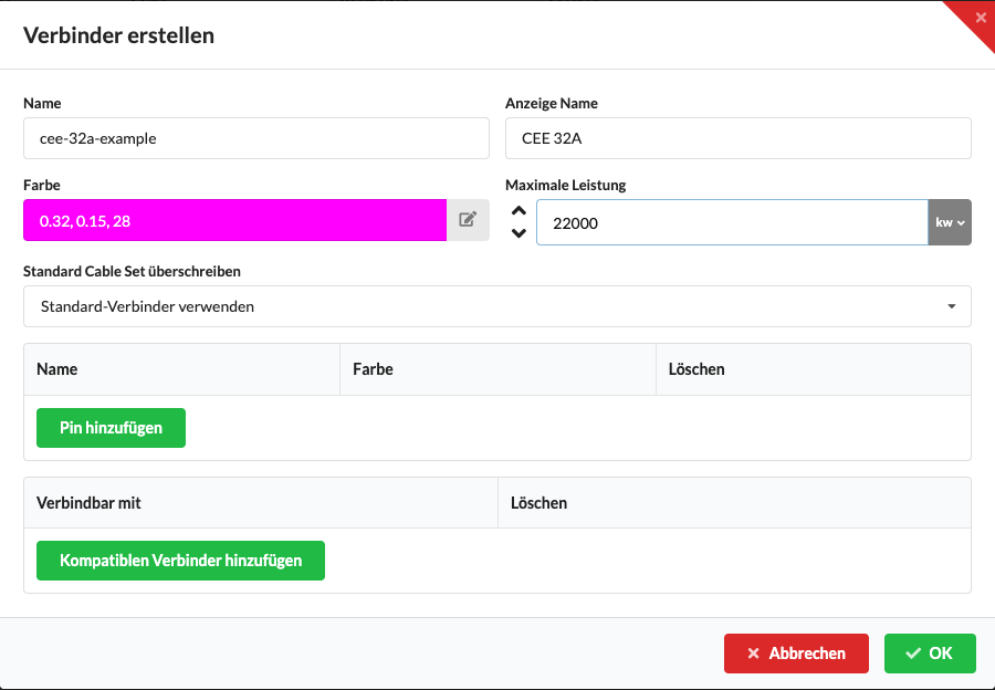
You can edit or delete custom connectors in the list. Connectors supplied as defaults are protected. When saving, you can enable Use Default Connectors to apply the default cable set. Override Default Cable Set replaces existing cable sets on objects that use the edited connector; enable this option only when those existing assignments should be replaced.
| Field / control | Description |
|---|---|
| Universal Name | Unique name of the connector. |
| Display Name | Connector label shown in the interface. |
| Data Connector | Indicates a data connector rather than an electrical connector. |
| Add Pin | Adds a pin to the connector. |
| Select Compatible Connectors | Sets which connectors can be connected to this pin. |
| Override Default Cable Set | Dropdown for selecting a cable set. Use Default Connectors keeps the default cable set selected. When you change an existing connector, Production Assist asks whether to apply the change to objects using that connector. |