

A corner block (boxcorner) connects the adjoining trusses, but does not automatically provide sufficient spatial bracing. Under wind load, the frame can move laterally or the corner block can be subjected to high bending loads.
A corner brace, meaning a diagonal brace at the corner, forms a triangle with the adjoining components. This directs part of the lateral action through the diagonal as axial force and relieves the corner block.
A pipe is suitable when the real assembly uses a tube or corresponding rigid brace capable of carrying both compression and tension.
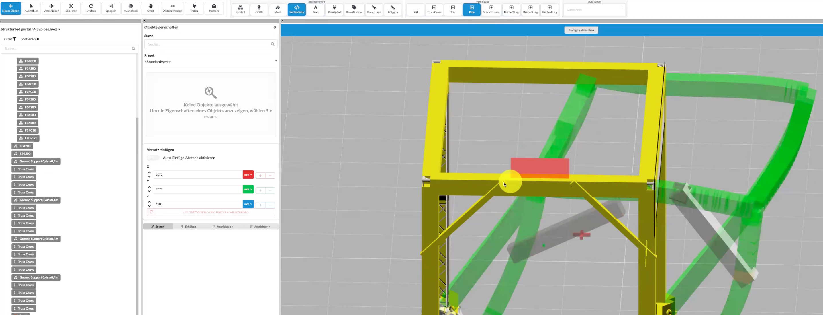
The pipe endpoints must be connected to the intended structural nodes. A diagonal that merely appears to touch a truss does not transfer force in the calculation.
If the new pipe remains gray in the Renderer, it often lacks a valid cross section. Check the Object Properties and the displayed structural errors. Use the cross section of the corner brace installed in reality rather than blindly copying one from an example.
A diagonal rope can also brace the frame effectively when it runs from the corner area to a suitable lower attachment or ballast point. The resulting triangle converts the lateral movement into axial force in the rope.
Keep the following in mind:
A single rope diagonal may only be considered sufficient if it is effective for the investigated load case and all other governing load cases are also covered by suitable components.
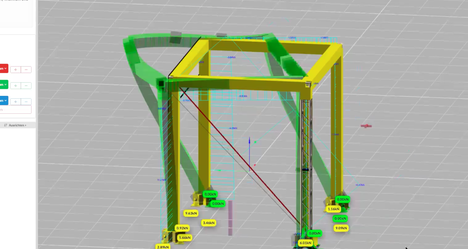
A larger base plate and additional ballast can improve the support condition at the floor. This can reduce the bending moment at the upper corner block because a larger share of the action is already resisted at the base.
However, this measure has a different structural effect from a corner brace:
| Measure | Effect in the model | Important prerequisite |
|---|---|---|
| Rigid corner brace | Transfers tension and, where applicable, compression through a diagonal | The real component and its connections must be capable of carrying these forces. |
| Rope diagonal | Transfers tensile force and forms a triangle for one load direction | The rope must be tensioned and attached at the actual connection point. |
| Larger base plate or ballast | Changes support conditions, uplift resistance, and overturning behavior at the base | Weight, dimensions, friction, and anchoring must be applied correctly. |
Ballast does not automatically replace missing diagonal bracing. Likewise, a support in the model must not resist tension if it is not anchored in the real assembly.
Check the entire structural system after every change:
The result is plausible if the diagonal actually carries force, the lateral deformation decreases, and no new impermissible loading occurs at another component or support.
Note: Model checking does not replace a structural verification or qualified assessment of the real connections. In particular, compression braces, ropes, ballast, and anchors may only be applied using their verified actual properties.