Tutorial: Create Power and DMX Patch Lists#
In this tutorial, you connect fixtures to a power distributor, assign DMX universes and addresses, and create the corresponding assembly sheets. You then save a reusable worksheet template and export a list as a PDF or CSV.
The screenshots in this tutorial mostly show older English interfaces. The steps use the current German menu and field labels. For other connection types and export options, see Electrical Planning, Network Planning, and Worksheets and Overviews.
Prerequisites#
- Insert fixtures and suitable power distributors into the drawing. Their symbol definitions must contain appropriate electrical connections.
- For the DMX patch, fixtures must have DMX connections and a suitable DMX mode. Check the DMX Footprint when addressing multiple devices in sequence.
- A FID helps distinguish fixtures in tables and selection lists. It is not required to assign a power connection.
- Connect a power source to the distributor if you also want to check the power utilization. Calculation is not required just to assign the connections.
1. Connect Fixtures to a Power Distributor#
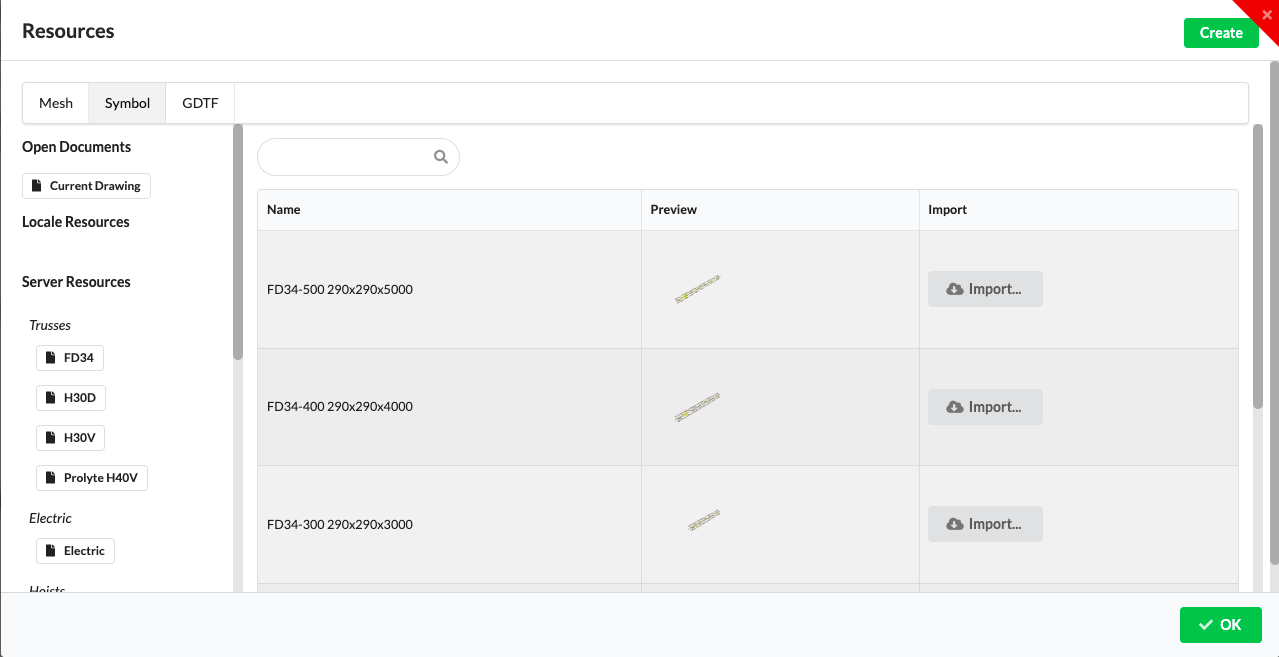
If needed, insert a distributor, such as a plugbox, using Toolbar → New Object and the Symbol resource type. Select a suitable resource from the library and place it in the drawing. Resource selection and insertion are described under New Object.
You can assign connections either on the fixture or on the distributor:
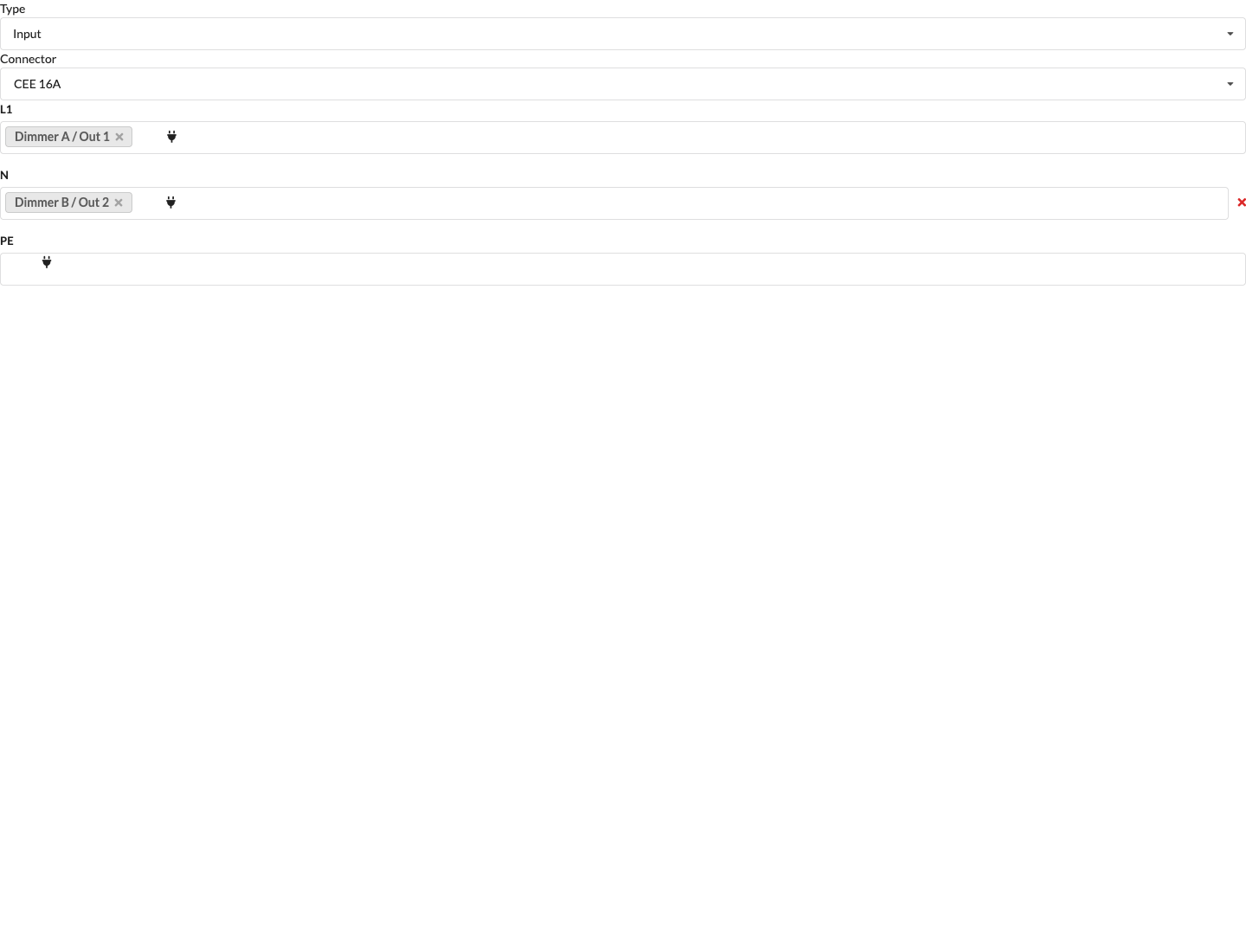
- Assign on the fixture: Select the fixture. Open Object Properties → Power Planning and choose the appropriate free distributor input in the IN field.
- Assign on the distributor: Select the distributor. Open Object Properties → Power Planning and choose the fixture's input at the appropriate output.
- Also connect the distributor's input to an upstream power source or distributor if you want to represent the complete supply path.
- Check the connection in the patch field. Connections that are already assigned are marked there. Remove an existing assignment first if you want to change it.
You can search by name, fixture ID, or object ID. A plugbox can have multiple connections; select the appropriate one by its name and number.
Check the connection status in the Scene Tree or in the Electrical Wiring Diagram. Electrical Planning describes manual and automatic wiring in full.
2. Enter the DMX Universe and Address in the Table#
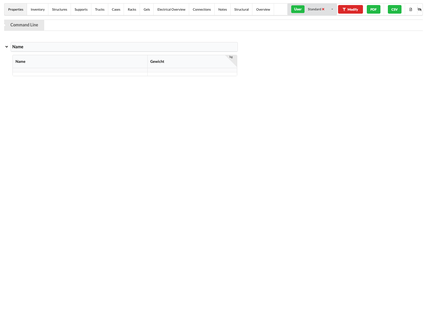
- Open Window → Worksheets and select the Properties view.
- Under Templates, select the Data Patch template. It displays fixture data such as FID, Name, DMX Universe, Relative DMX Address, DMX Mode, and DMX Footprint, and filters the table to fixtures. The template selects columns and filters; it does not assign addresses.
- Check that the expected fixtures appear in the table. If needed, use the Filter area to select additional or different object types.
- Enter the universe in the DMX Universe field. You can select multiple relevant table cells and assign them the same universe value.
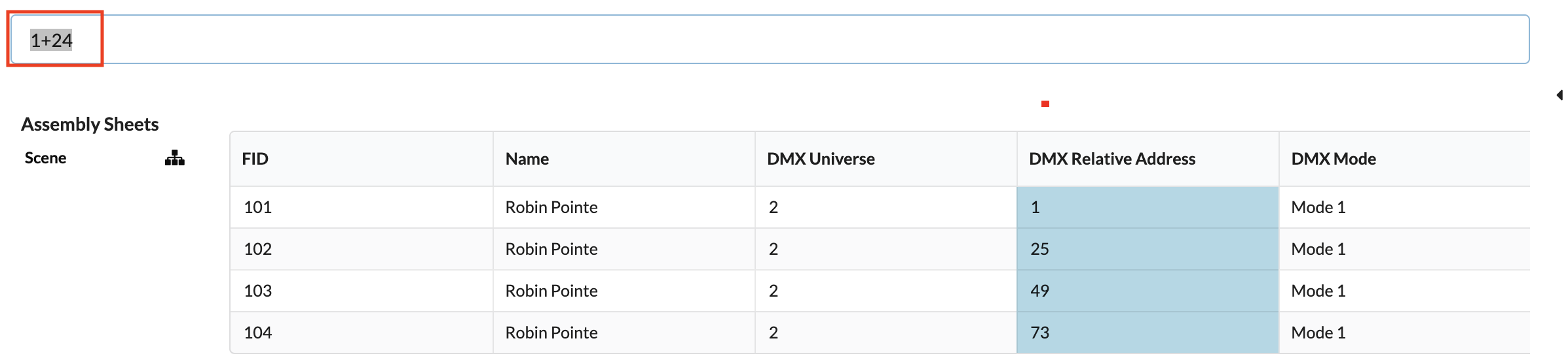
- Enter the start address in the Relative DMX Address field. To address multiple selected fixtures, enter a start address followed by a plus sign, for example
1+. Production Assist automatically increments the next address by the footprint of each fixture in the selected DMX mode. You can also enter 1+24 to specify a fixed spacing of 24 channels.
- Confirm the entry with Enter and check the values in the affected rows. In particular, make sure the addresses are in the intended universe and the DMX mode matches the connected device.

If a property column is missing, enable the field under Properties or use a suitable template. You do not need to add a screenshot for this: the current field list and table controls are described under Properties Worksheet.
3. Create Assembly Sheets for Areas#
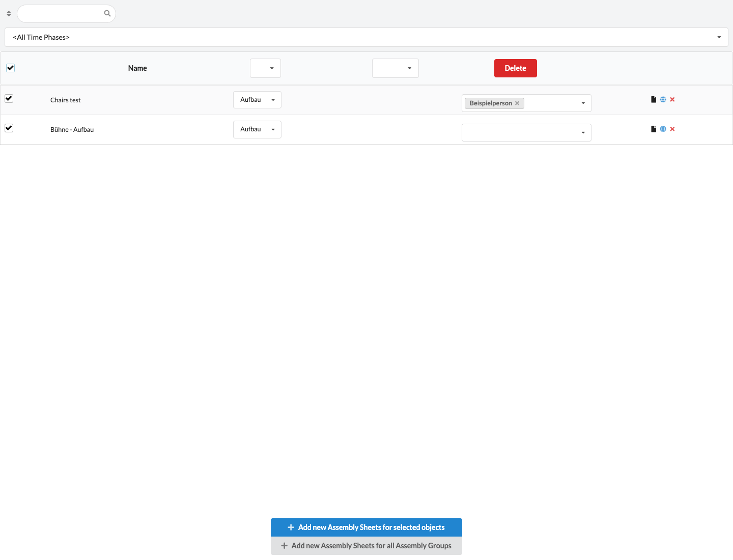
An assembly sheet limits the table to objects in an assembly group or another drawing area. Select the relevant area and create the assembly sheet through the context menu or Navigation:
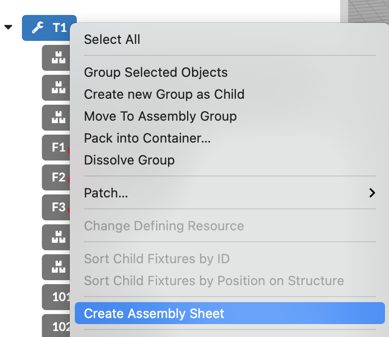
- In the Scene Tree, select the desired assembly group, open the context menu, and click Create Assembly Sheet.
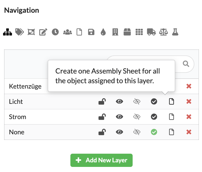
- For objects on a layer or class, use the assembly-sheet icon in the corresponding row in Navigation.
- After creating the sheet, check for it under Assembly Sheets in the Worksheet window. Select it to see its objects in the table.
When multiple objects or assembly groups are selected, the command can create a separate assembly sheet for each selected item. Select only the area you want. Other ways to create sheets, along with filters and sheet options, are described under Create Assembly Sheets.
4. Save a Worksheet Template#
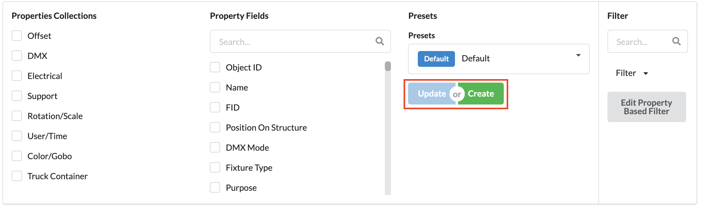
Worksheet Templates save the table view, for example its columns, groupings, and filters. They are different from the object Presets in Navigation.
- In the Properties area, select the required columns and set filters and groupings.
- Under Templates, click Create to save the current table view with a name.
- If you have changed an editable template, click Update to overwrite its view.
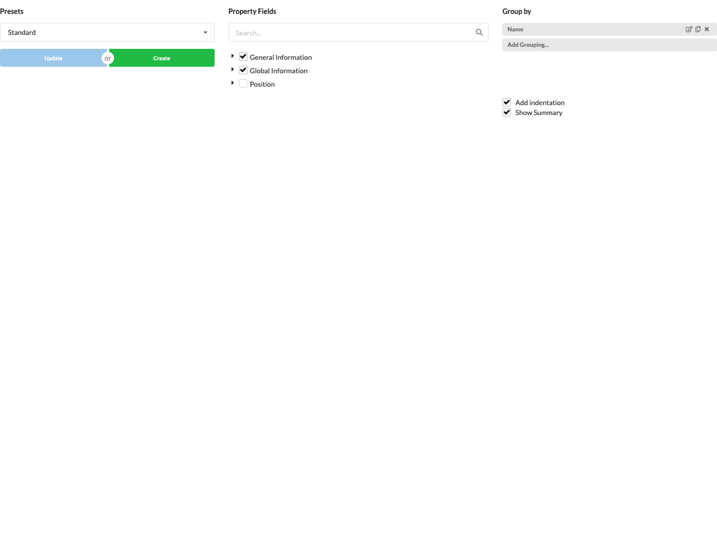
For details about columns, grouping, and table templates, see Properties Worksheet.
5. Export a Worksheet as PDF or CSV#
- Under Assembly Sheets, select Scene for the entire drawing or a specific assembly sheet for its objects.
- Check the list view, filters, columns, and sort order.
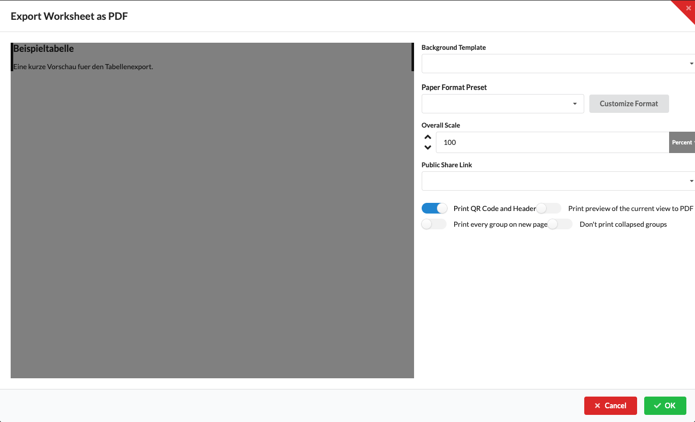
- In the Worksheets window, click PDF. In the Export Assembly Sheet as PDF dialog, check the preview, select Template Background and Paper Templates if needed, and set the Scale and print options. For an online project, Public Link to Share offers an existing or newly created sharing link. The first time you open the dialog after opening the Worksheet Window, Print QR Code and Header is enabled; Print Current View as PDF Preview, Print Each Group on a New Page, and Do Not Print Collapsed Groups are disabled. When you reopen the dialog in the same window, your toggle settings are retained. A QR link requires a linked online project; the selected sharing link determines access. Click OK to start the export, then choose the filename and location in the save dialog. Cancel closes the export dialog without creating a PDF. See Export Lists as PDF for more options.
- Use CSV if you want to process the displayed table in another program.
- Open the exported file and check the values, page layout, and scope before printing or sharing it.
The PDF button for a single list is different from File → Export Worksheets as PDF..., which lets you assemble a multipage document from text, assembly sheets, and views. For details, see Export Lists as PDF, Export a Table as CSV, and Assemble Documentation as PDF.