

The menu bar brings together Production Assist's most important work commands. Depending on the platform, license, open drawing, and active integration, individual menus or commands may be shown or hidden.
Typical menu items are:
The macOS desktop app also includes the Production Assist app menu.
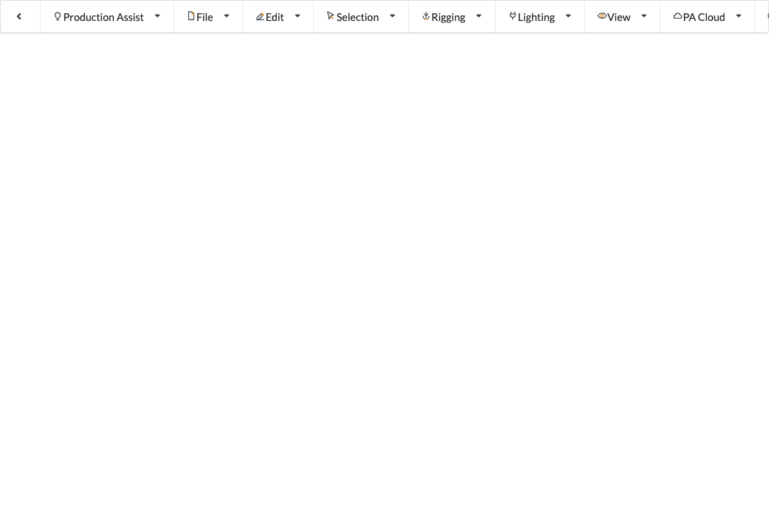
The main menus are File, Edit, Selection, Rigging, Lighting, View, Window, PA Cloud, and Help. The Window menu is a native desktop menu and therefore does not appear in the rendered menu bar screenshot. The integration menus for Vectorworks and AutoCAD/BricsCAD are available depending on the installed and active host integration. The Development menu with diagnostic commands appears only in Development builds; the additional Production Assist app menu is available on macOS.
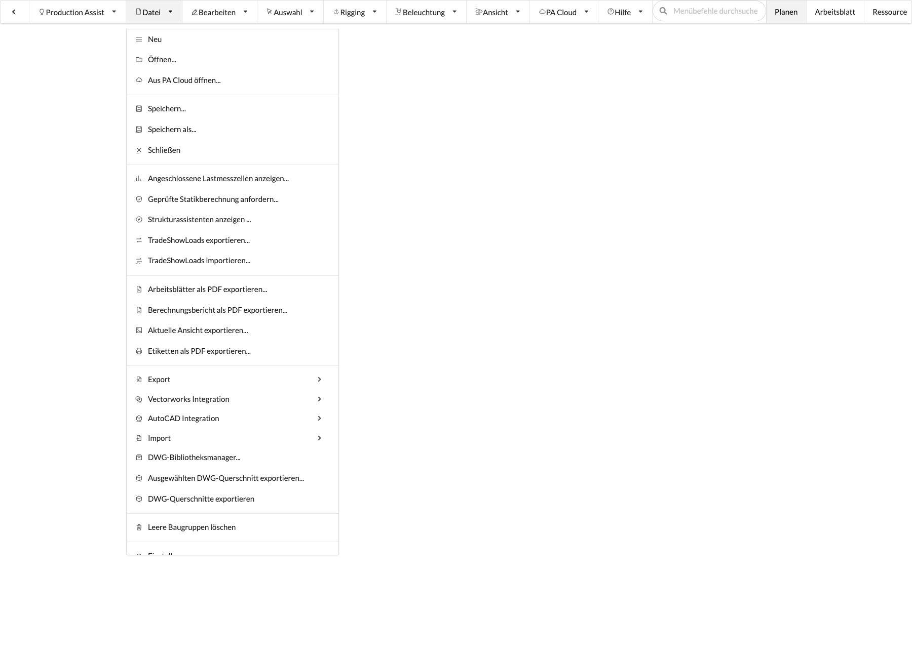
In the File menu, you manage drawings, import and export data, and access central output functions.
| Command | What happens | Requirement |
|---|---|---|
| New | Creates a new, empty drawing. | Desktop app or host integration; not a browser view alone. |
| Open... | Opens an existing Production Assist drawing from your computer. | Access to a local file. |
| Open from PA Cloud... | Loads a drawing from an online project into your workspace. | Signed-in account and access to a PA Cloud project. |
| Recently opened | Opens a previously used file directly from the recent files list. | At least one previously opened file. |
| Save... | Saves the current drawing to its existing file path. | Open drawing with write access. |
| Save as... | Saves the current drawing as a new file or under a new name. | Open drawing. |
| Close | Closes the current drawing. | Open drawing in the desktop app or host integration. |
| Command | What happens | Requirement |
|---|---|---|
| Request verified structural calculation... | Opens the dialog for external review of a structural calculation. There, you review the price, enter billing and project details, and submit the order, or download a quote first. The Guide to requesting a verified structural calculation explains the requirements, process, and status display. | Signed-in account with access to a project linked to a PA Cloud project and workspace; an available billing/reporting account is also required to place an order. |
| Show connected load cells... | Opens the Connect load cells dialog, where you set up supported measurement systems and start or stop monitoring. To see current measurements, the connection and device assignment must be set up. See Connect load cells and check measurements for details. | Open drawing; a connected and assigned measurement system is required to retrieve measurements. |
| Show structure wizard ... | Opens the Structure Wizard to select presets for wind and area loads, ballast, and floor loads. The selections for area loads, ballast, and floor loads are not reliably applied in the current program code; after selecting OK, check the affected object and load-combination settings. The wind-load selection is set in the load-combination settings. | Open drawing. |
| Export TradeShowLoads... | Opens the fields for the exhibition, hall, booth, and company. Production Assist then calculates the drawing and saves the load overview and the support points for motors and bridles, together with this exhibition information, in a .tsle file. The TradeShowLoads guide describes the inputs and process. | Drawing with calculable loads and supports. |
| Import TradeShowLoads... | Opens a .tsle file for review and creates new objects from its points; the load overview is display-only. The TradeShowLoads guide explains point mapping and shows the import dialog. | Existing .tsle file; symbol mapping for points if needed. |
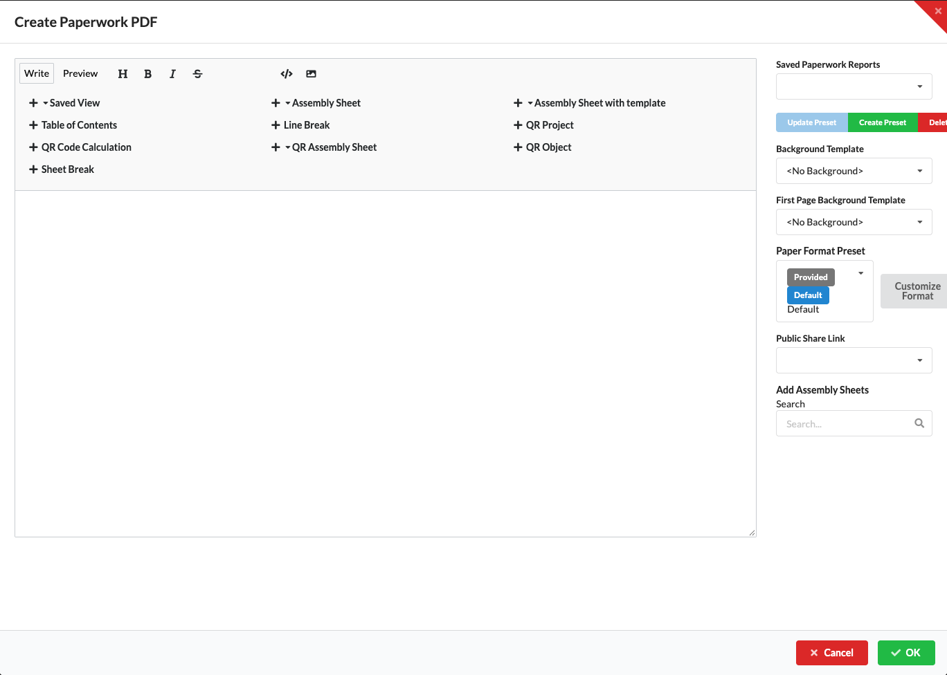
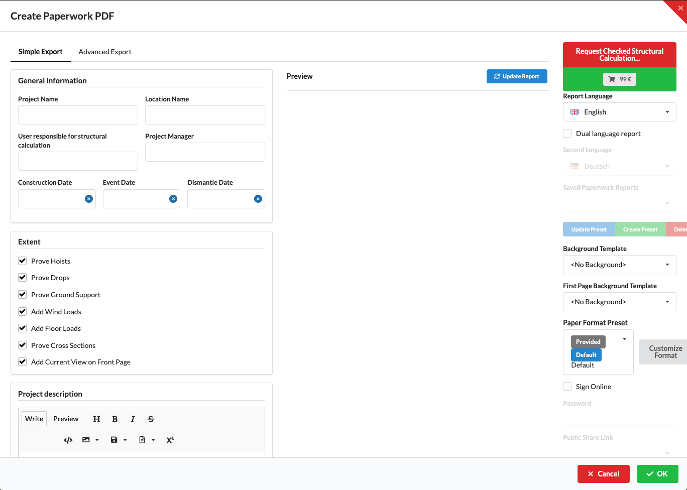
| Export worksheets as PDF... | Opens Export documentation to combine text, Assembly Sheets, and saved views in a PDF; see Compile documentation as PDF. The PDF button in the Worksheet Window, by contrast, exports the selected list view. | Open drawing; to include Assembly Sheets or views, those items must be present. |
| Export calculation report as PDF... | Exports the structural report with results and evidence. See Export the calculation report for details. | A structural calculation has been performed or calculable results are available. |
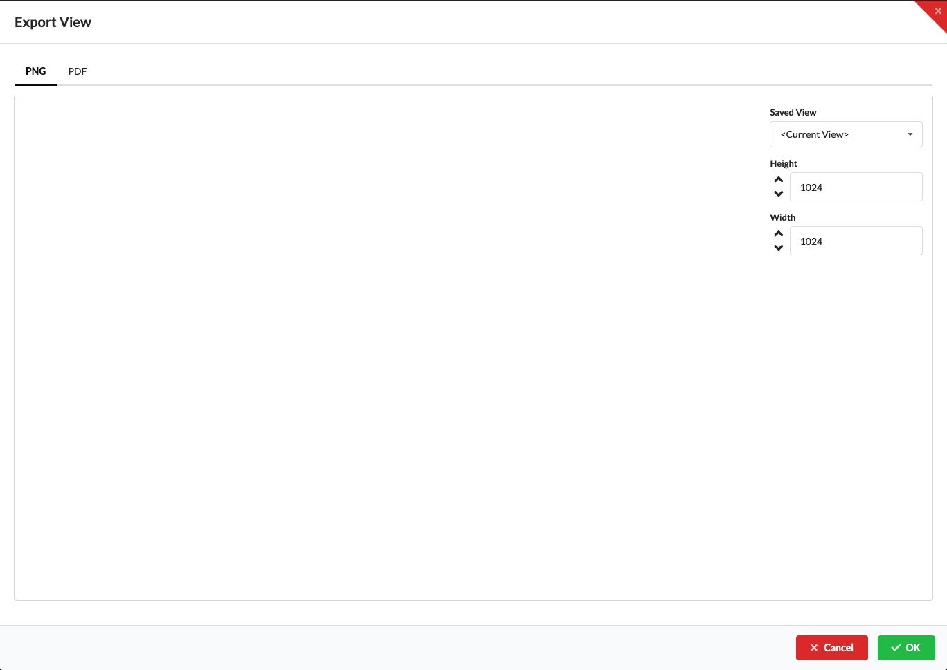
| Export current view... | Opens Export view. Select PNG or PDF and a saved view on the corresponding tab. On the PNG tab, you can set the image width and height; both fields start at 1024. On the PDF tab, you can also select a print label as a background and a public project link. The paper dimensions are based on the print label and are set to 210 × 297 mm when no print label is selected. Select OK to save the output. | Open drawing with the desired saved view; to use a public project link, the drawing must be linked to an online project. |
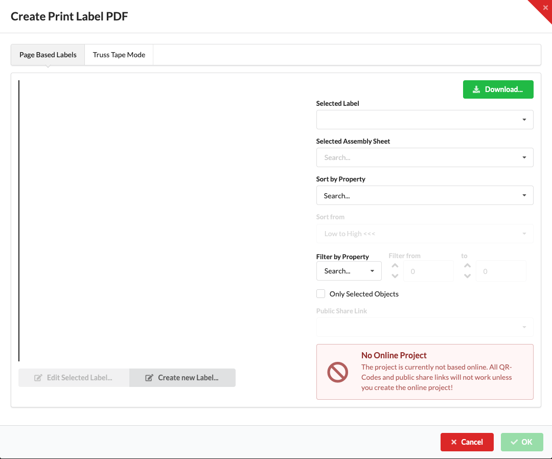
| Export labels as PDF... | Creates a printable PDF from existing label templates. See Export labels as PDF for details. | Label templates or assigned label data exist. |
For the complete MVR and GDTF exchange workflows, see MVR and GDTF. The other export formats and their requirements are described with each command.
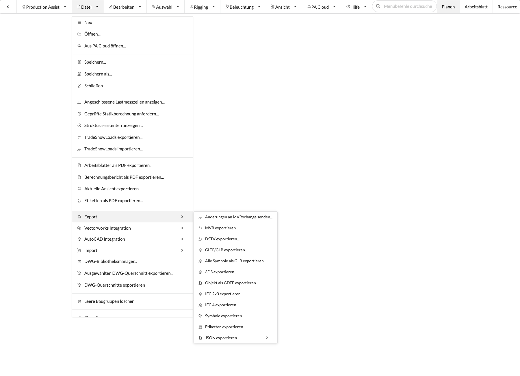
| Command | What happens | Requirement |
|---|---|---|
| Send changes to MVRxchange... | Publishes an MVR revision of the current drawing to the connected local MVRxchange group; see MVRxchange. | Active connection to an MVRxchange group on an accessible network. |
| Export MVR... | Exports the drawing as an MVR file for exchange with other systems. | Drawing with exportable MVR data. |
| Export DSTV... | Exports suitable steel or structural information as a DSTV file. | Drawing contains DSTV-relevant components. Spring connections are not supported in structural exports; the export is canceled for such models. See Spring connections. |
| Export GLTF/GLB... | Exports the scene as a 3D file in GLTF or GLB format. | Open drawing with 3D content. |
| Export all symbols as GLB... | Exports each symbol definition in the active drawing as a separate GLB file in a selected folder. | Desktop app with an open drawing; the folder must be writable. |
| Export 3DS... | Exports the scene as a 3DS file. | Open drawing with 3D content. |
| Export object as GDTF... | Exports a suitable object or fixture as a GDTF file. | Matching fixture or symbol with sufficient device data. |
| Export IFC 2x3... | Exports the drawing in IFC 2x3 format. | IFC-capable geometry and the desired exchange in a BIM context. |
| Export IFC 4... | Exports the drawing in IFC 4 format. | IFC-capable geometry and the desired exchange in a BIM context. |
| Export symbols... | Opens the multi-selection of symbol definitions. Select the desired entries; OK then opens the file dialog for export. An empty selection is allowed, but does not create usable resources. | Open drawing; for a meaningful export, it must contain symbol definitions. |
| Export labels... | Opens the same multi-selection for print labels. Select the desired entries; OK then opens the file dialog for export. An empty selection is allowed, but does not create usable resources. | Open drawing; for a meaningful export, it must contain print labels. |
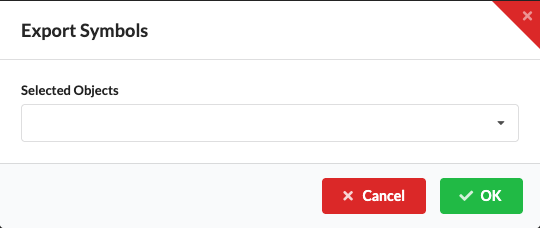
Open File → Export → Export symbols... or File → Export → Export labels.... Both commands use the Export Symbols dialog. In the Symbols field, select one or more resources from the active drawing. For Export labels..., the list contains print labels even though the title and field label remain the same. The selection field accepts multiple entries; the object selection in the plan does not affect the resource list.
Select OK to pass the selection to the file dialog that follows. There, set the save location and filename for the .lrwx file. Production Assist writes the selected symbol definitions or print labels to this file. Cancel or the close icon exits the dialog without exporting. The selection may be empty; in that case, the generated file contains no selected resources and is not useful for further use.
The example shows the dialog for symbol definitions with an empty list. If the drawing contains entries, their names appear in the multi-selection field. When exporting print labels, the list is also dynamic even though the Symbols label remains unchanged.
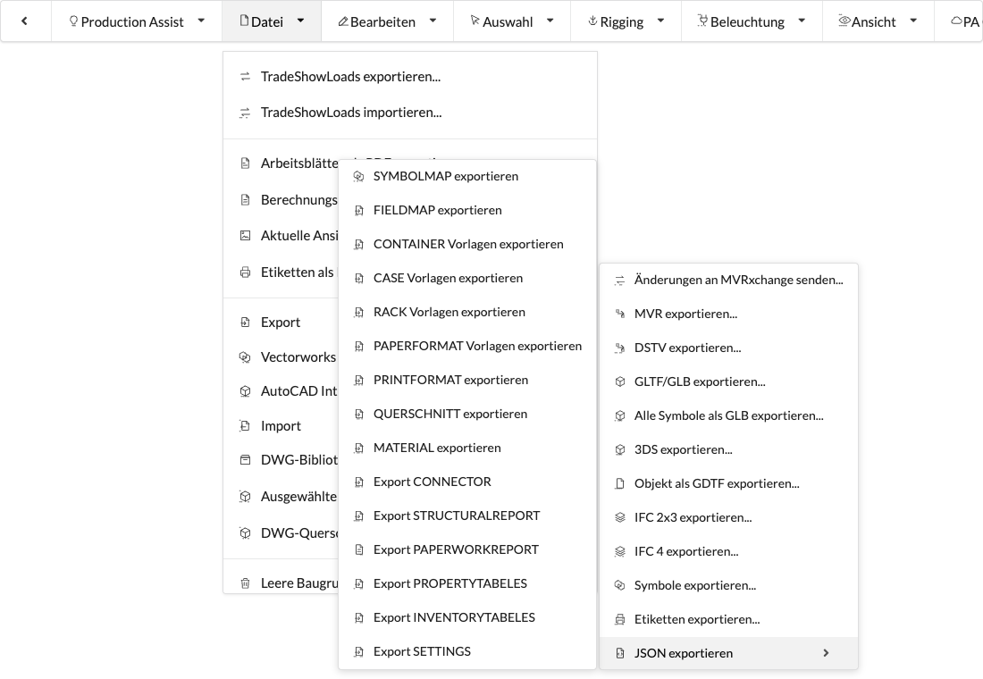
| Command | What happens | Requirement |
|---|---|---|
| Export SYMBOLMAP | Exports symbol mappings as a JSON file. | Existing symbol mappings in the drawing or library. |
| Export FIELDMAP | Exports field mappings as a JSON file. | Existing field definitions or mappings. |
| Export CONTAINER templates | Exports truck or container templates as JSON. | Existing container or truck templates. |
| Export CASE templates | Exports case templates as JSON. | Existing case templates. |
| Export RACK templates | Exports rack templates as JSON. | Existing rack templates. |
| Export PAPERFORMAT templates | Exports paper format templates as JSON. | Existing print or paper format templates. |
| Export PRINTFORMAT | Exports print formats as JSON. | Existing print formats. |
| Export CROSS SECTION | Exports cross-section definitions as JSON. | Existing cross-section data. |
| Export MATERIAL | Exports material definitions as JSON. | Existing material data. |
| Export CONNECTOR | Exports connector definitions as JSON. | Existing connector definitions. |
| Export STRUCTURALREPORT | Exports templates or data for structural reports as JSON. | Existing report templates or exportable report data. |
| Export PAPERWORKREPORT | Exports templates or data for Paperwork reports as JSON. | Existing Paperwork templates or report data. |
| Export PROPERTYTABLES | Exports templates for property tables as JSON. | Existing table templates. |
| Export INVENTORYTABLES | Exports templates for inventory tables as JSON. | Existing inventory tables or templates. |
| Export SETTINGS | Exports settings as a JSON file. | Exportable app, project, or print settings. |
The Vectorworks Integration item groups commands for reading and updating the Vectorworks plan and for preparing and writing back symbols. These commands require the Vectorworks integration. Setup and workflow are described in the Vectorworks guide.
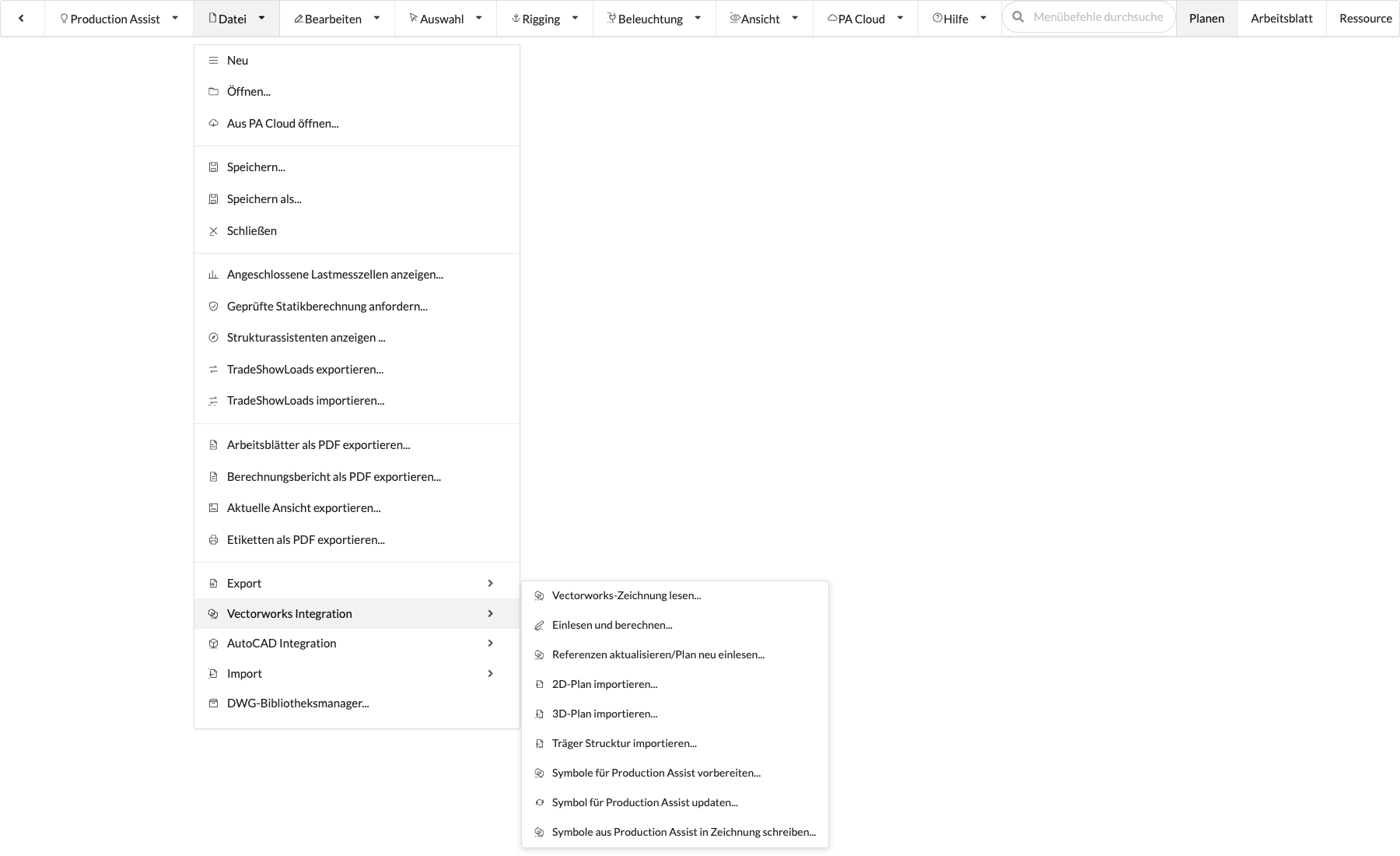
| Command | What happens | Requirement |
|---|---|---|
| Read Vectorworks drawing... | Reads the current or linked Vectorworks drawing into Production Assist. | Active Vectorworks integration and accessible drawing data. |
| Read and calculate... | Rereads the Vectorworks drawing and immediately starts a structural calculation. | Vectorworks integration and calculable structural data. |
| Update references/reread plan... | Updates references or rereads the host drawing. | Vectorworks data already linked. |
| Import 2D plan... | Imports a 2D plan from the host application. | Active Vectorworks integration with suitable plan content. |
| Import 3D plan... | Imports 3D geometry from the host application. | Active Vectorworks integration with 3D data. |
| Import beam structure... | Imports structural components from the host application. | Active integration and existing structure objects. |
| Prepare symbols for Production Assist... | Prepares host symbols for use in Production Assist. | Suitable symbols in the host application. |
| Update symbol for Production Assist... | Updates symbol definitions already prepared from the host application. | Existing, linked symbols. |
| Write symbols from Production Assist into drawing... | Writes symbol information from Production Assist back to the host drawing. | Active integration and target drawing with write access. |
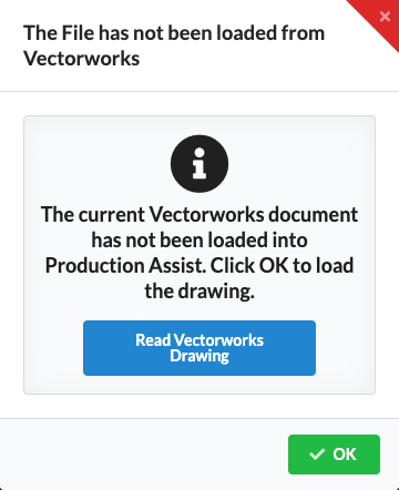
If Vectorworks reports that the file was not loaded, Production Assist displays a notification dialog. Select Read Vectorworks drawing or OK to read the host drawing. The dialog appears only if the host call reports a file that was not loaded.
Installation and CAD-specific workflows are described in the AutoCAD and BricsCAD installation quick start and the shared CAD guide for AutoCAD, BricsCAD, and ZWCAD.
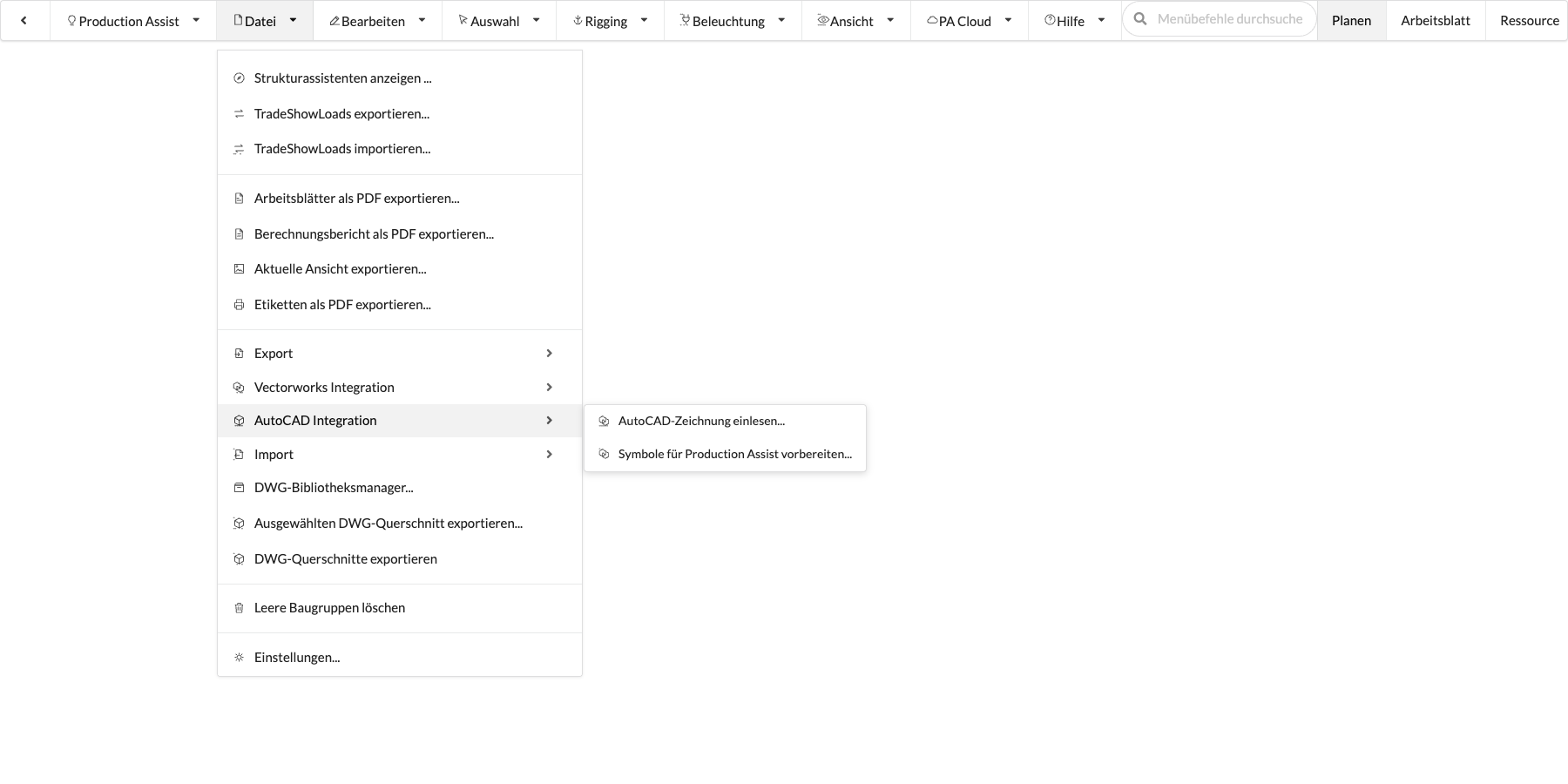
| Command | What happens | Requirement |
|---|---|---|
| Read AutoCAD drawing... | Reads an AutoCAD drawing into Production Assist. | Active AutoCAD integration. |
| Prepare symbols for Production Assist... | Reads placed AutoCAD or BricsCAD blocks, creates local symbol definitions when their geometry can be evaluated, and opens the Symbol Map for mapping. In BricsCAD, the menu name remains AutoCAD Integration. | Loaded CAD plug-in, active DWG and connection to the desktop app; a suitable Production Assist symbol for mapping. |
For MVR, GDTF, and fixture workflows, see MVR and GDTF; the SketchUp extension explains SketchUp import and host integration.
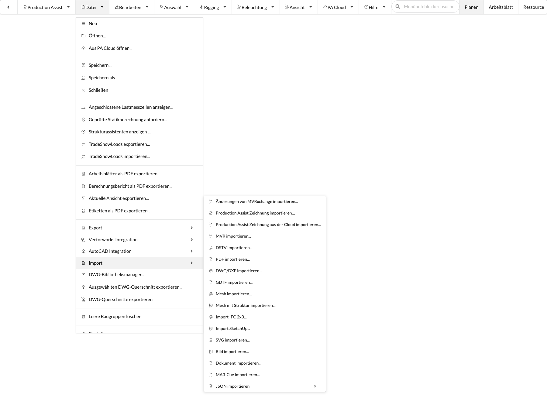
| Command | What happens | Requirement |
|---|---|---|
| Import changes from MVRxchange... | Opens MVRxchange Settings. There, request another group's revision and then import it through the Symbol Map. See MVRxchange on a local network for requirements and steps; it also shows the current dialog. | Connection to an MVRxchange group on an accessible network and a revision published there. |
| Import Production Assist drawing… | Imports content from another Production Assist drawing. | Import file available. |
| Import Production Assist drawing from the cloud... | Imports content directly from a cloud drawing. | Online project with the corresponding source file. |
| Import MVR... | Imports an MVR file into the current drawing. | Existing MVR file. |
| Import DSTV... | Imports DSTV data into the current drawing. | Existing DSTV file. |
| Import PDF... | Imports a PDF, for example as a plan background. | Existing PDF file. |
| Import DWG/DXF... | Imports a DWG or DXF file. | Desktop app with a DWG or DXF file available. |
| Import GDTF... | Opens a .gdtf file and creates its fixture type in the current drawing. To place it afterward, select New Object → GDTF. | Existing GDTF file; importing alone does not place a fixture in the plan. |
| Import mesh... | Creates a mesh resource in the current drawing. Place it afterward using New Object → Mesh; supported file extensions are listed in the format overview. | Existing 3D file in a supported format. |
| Import mesh with structure... | Imports a mesh scene with its objects and hierarchy into the current drawing; see the format overview. | Existing scene file in a supported format. |
| Import IFC 2x3... | Imports IFC data in 2x3 format. | Existing IFC file. |
| Import SketchUp... | Imports a SketchUp model. | Existing SketchUp file. |
| Import SVG... | Imports vector graphics in SVG format. | Existing SVG file. |
| Import image... | Imports an image as a resource or plan content. | Existing image file. |
| Import document... | Imports an external document into the project. | Existing file and desired project reference point. |
| Import MA3 cue... | Imports cue or sequence data and supported fixture values from a grandMA3 XML file into timelines and presets in the active drawing; see grandMA3 cue import. | Existing .xml file; an existing timeline is required for individual cue data, and matching fixtures must be in the drawing for fixture values. |
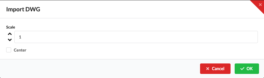
Open File → Import → Import DWG/DXF... and select the source file. In the Import DWG dialog, specify how the geometry is imported. OK starts the import; afterward, check a known dimension to see whether the scale matches the source file's unit.
| Field / button | Effect and limitation |
|---|---|
| Scale | Multiplies the imported coordinates by this factor. The initial value is 1. Use a positive factor that matches the source file's unit; 0 does not start the import, but opens the scale prompt again. Then check a known dimension. |
| Center | During DWG import, moves the center of the bounding box to the origin. The option is off by default. The field also appears during DXF import, but has no effect there. |
| OK | Starts the import with the entered values. |
| Cancel | Closes the dialog without starting the import from this dialog. |
During DXF import, you can center the file in a CAD program before importing it. The Center checkbox in Production Assist does not move DXF content.
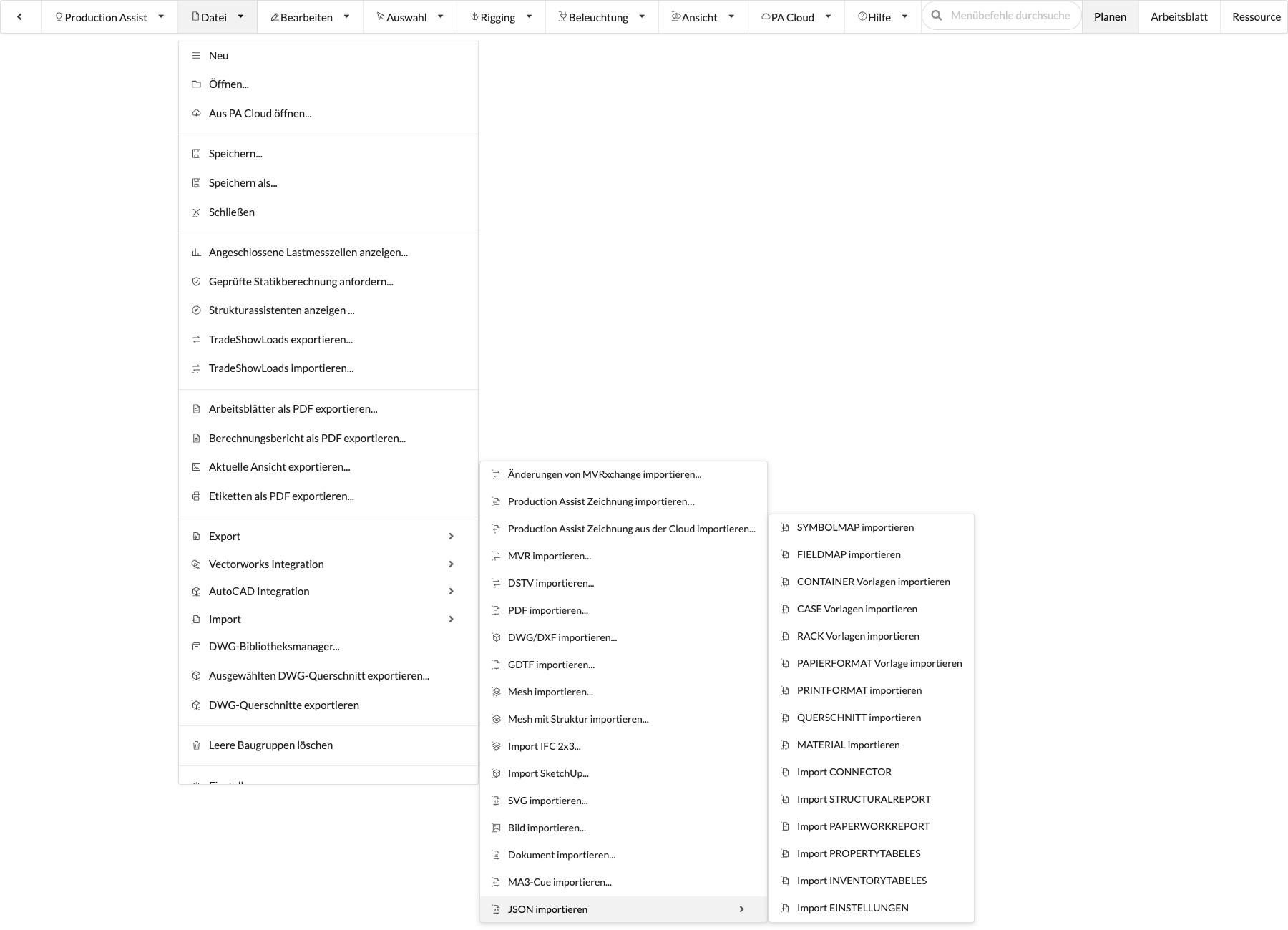
| Command | What happens | Requirement |
|---|---|---|
| Import JSON | Opens the general JSON import for supported data types. | JSON file available. |
| Import SYMBOLMAP | Imports symbol mappings from JSON. | Matching JSON file with symbol mappings. |
| Import FIELDMAP | Imports field mappings from JSON. | Matching JSON file with field definitions. |
| Import PRINTFORMAT | Imports print formats from JSON. | Matching JSON file with print formats. |
| Import CONTAINER templates | Imports truck or container templates from JSON. | Matching JSON file with templates. |
| Import CASE templates | Imports case templates from JSON. | Matching JSON file with templates. |
| Import RACK templates | Imports rack templates from JSON. | Matching JSON file with templates. |
| Import PAPERFORMAT template | Imports paper format templates from JSON. | Matching JSON file with paper formats. |
| Import CROSS SECTION | Imports cross-section definitions from JSON. | Matching JSON file with cross-section data. |
| Import MATERIAL | Imports material definitions from JSON. | Matching JSON file with material data. |
| Import CONNECTOR | Imports connector definitions from JSON. | Matching JSON file with connector data. |
| Import STRUCTURALREPORT | Imports structural report templates or report data from JSON. | Matching JSON file with report data. |
| Import PAPERWORKREPORT | Imports Paperwork templates or report data from JSON. | Matching JSON file with report data. |
| Import PROPERTYTABLES | Imports templates for property tables from JSON. | Matching JSON file with table templates. |
| Import INVENTORYTABLES | Imports templates for inventory tables from JSON. | Matching JSON file with inventory data or templates. |
| Import SETTINGS | Imports saved settings from JSON. | Matching JSON file with compatible settings. |
| Command | What happens | Requirement |
|---|---|---|
| Delete empty Assembly Groups | Removes empty Assembly Groups. Caution: if an empty Assembly Group is the last child of its parent Assembly Group, the current command also includes that parent Assembly Group for deletion. Deleting a parent Assembly Group also removes its child objects. Therefore, check the affected branch in the Scene Tree before using the command. | Drawing with empty Assembly Groups; use only after checking the affected branch. |
| DWG Library Manager... | Opens the standalone DWG Library Manager to check DWG truss folders, assign cross sections, and transfer completed files to the target library. | Desktop app. |
| Export selected DWG cross section... | Exports the selected DWG cross section as a separate file. | Desktop app and a selected, exportable cross section. |
| Export DWG cross sections | Exports the available DWG cross sections as library files. | Desktop app. |
| Settings... | Opens the general app, project, and print settings. | Open drawing or accessible application settings. |
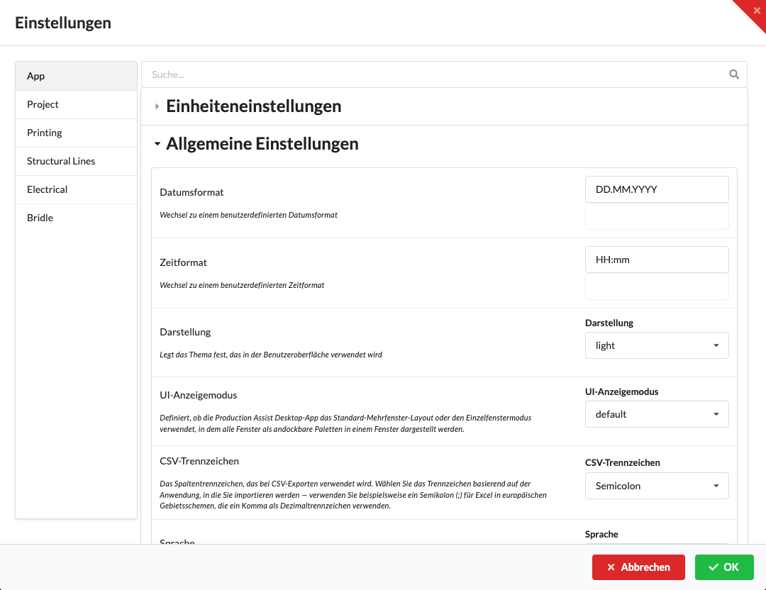
Important settings in this dialog include units, display options, rendering behavior, magnet visibility, display of static hints, and patching behavior.
The Edit menu contains commands for changing, renaming, and structuring your drawing.
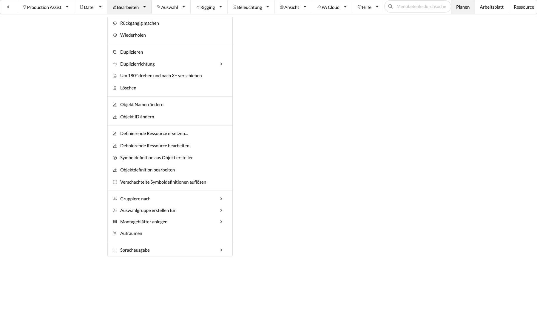
| Command | What happens | Requirement |
|---|---|---|
| Undo | Reverses the last change. | There is a change that can be undone. |
| Redo | Restores a previously undone step. | There is a step that can be redone. |
| Copy | Copies the current selection to the clipboard. | At least one selected object. |
| Paste | Inserts the clipboard contents. | Suitable content in the clipboard. |
| Cut | Removes the selection and places it on the clipboard. The current German translation spells the menu item with three “s” characters after “Au”. | At least one selected object. |
| Duplicate | Creates a copy of the selected objects. | At least one selected object. |
| Delete | Deletes the selected objects. | At least one selected object. |
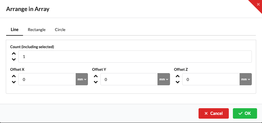
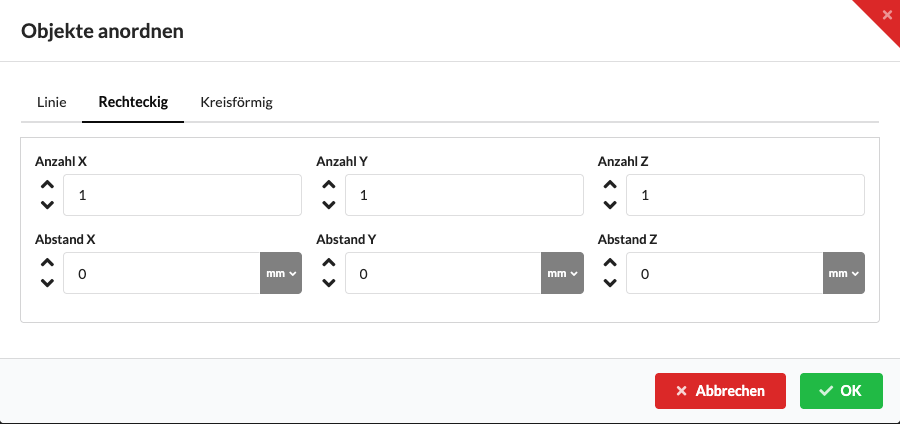
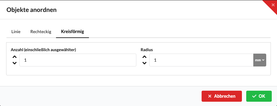
Open Arrange Objects from the context menu Duplicate and Arrange Selected Objects to create copies. To redistribute several selected objects, choose Edit → Arrange Selected Objects. Both routes show the Line, Rectangular, and Circular tabs. When creating copies, each original object remains and counts as the first position.
| Field / button | Effect and limitation |
|---|---|
| Line | Distributes the objects in a row. Distance X, Distance Y, and Distance Z together form the offset from one position to the next. |
| Rectangular | Distributes the objects in a grid. Count X, Count Y, and Count Z define the positions on each axis; their spacing is set with Distance X, Distance Y, and Distance Z. When creating copies, a grid of 2 × 3 × 1 creates six positions, including the original object. When arranging existing objects, the grid must have enough positions for the selection; a grid that is too small may not reliably map all objects. |
| Circular | Distributes the objects in the X/Y plane using Radius. The original object occupies the first point on the circle. |
| Count (including selected) | For new copies, sets the total count including the original object. A value of 3 creates two copies per original object. When arranging existing objects, the selection determines the count. In this mode, the displayed count for Circular is not evaluated. |
| Cancel | Closes the dialog without making a change. |
| OK | Creates the copies or arranges the existing selection according to the chosen pattern. |
The Count and Count X/Y/Z fields expect whole-number position counts; the dialog does not display range validation. Before selecting OK, check that the count and grid size fit your pattern. Spacing and radius use the current length unit.
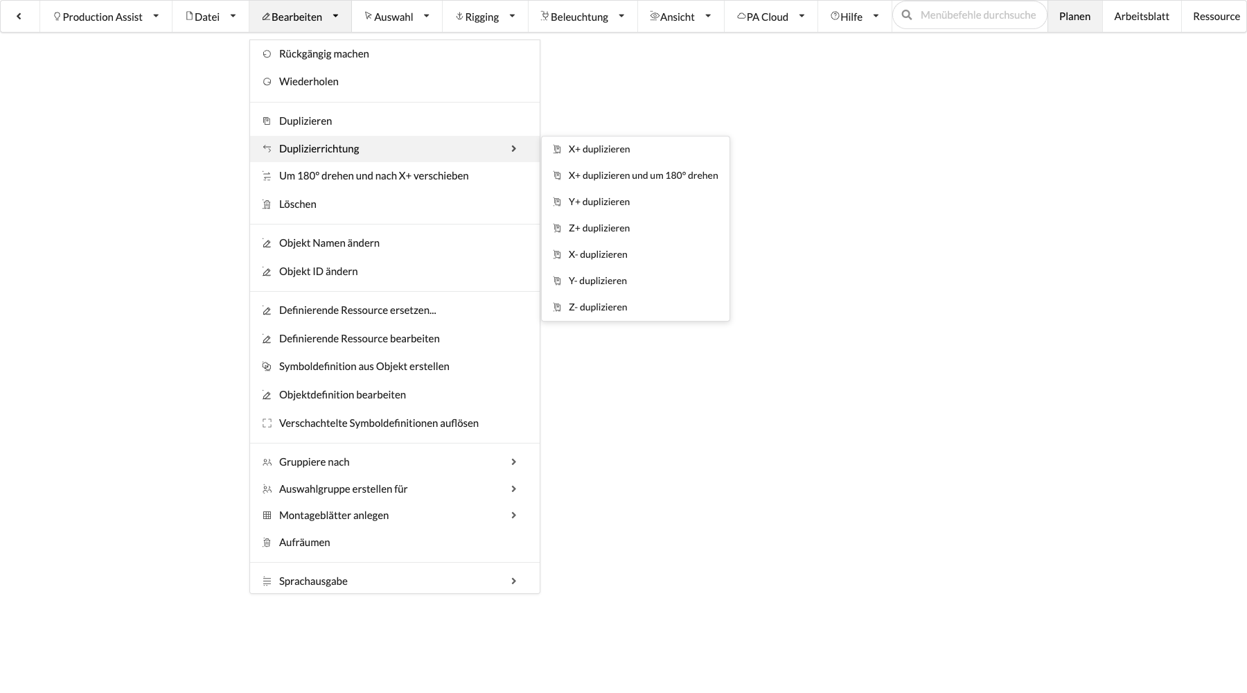
These commands create copies of the selection in the respective positive or negative X, Y, or Z direction. Production Assist uses the corresponding values in the Paste Offset window as the offset. The commands select the copies they create. To duplicate along an existing structure, use Place Objects on Structure instead.
| Command | What happens | Requirement |
|---|---|---|
| Duplicate X+ | Duplicates the selection in the positive X direction. | At least one selected object; uses the X value from Paste Offset. |
| Duplicate X+ and Rotate 180° | Duplicates the selection in the positive X direction and rotates the copies by 180°. | At least one selected object; uses the X value from Paste Offset. |
| Duplicate Y+ | Duplicates the selection in the positive Y direction. | At least one selected object; uses the Y value from Paste Offset. |
| Duplicate Z+ | Duplicates the selection in the positive Z direction. | At least one selected object; uses the Z value from Paste Offset. |
| Duplicate X- | Duplicates the selection in the negative X direction. | At least one selected object; uses the X value from Paste Offset. |
| Duplicate Y- | Duplicates the selection in the negative Y direction. | At least one selected object; uses the Y value from Paste Offset. |
| Duplicate Z- | Duplicates the selection in the negative Z direction. | At least one selected object; uses the Z value from Paste Offset. |
The host plug-ins also provide commands for copying and moving along the X, Y, and Z axes. In AutoCAD and BricsCAD, Copy and Move are available in the Production Assist ribbon; their command-line names are listed under AutoCAD and BricsCAD. For SketchUp and Vectorworks, use the commands in the respective SketchUp guide and Vectorworks guide. The Paste Offsets set the distance.
| Command | What happens | Requirement |
|---|---|---|
| Rename Object | Activates the name field of the selected object for direct editing. | Exactly one object or an unambiguous selection. |
| Change Object ID | Activates the ID field of the selected object for direct editing. | Exactly one object or an unambiguous selection. |
| Replace Defining Resource... | Replaces the underlying resource of a selected object. | Selection with a replaceable resource. |
| Edit Defining Resource | Opens the linked symbol or fixture resource in Edit Mode. Changes to a shared resource affect all linked drawing objects. | Selected object with a linked, editable resource. |
| Create Symbol Definition from Object | Creates a new symbol definition from the selected object. | Selection with a suitable object or geometry. |
| Edit Object Definition | Opens the selected drawing object's own geometry definition in Edit Mode. Edit this definition when the change should affect only this object. | Selected object with an editable definition. |
| Resolve Nested Symbol Definitions | Resolves the nested symbol definitions of the first selected object. If several objects are selected, only the first is processed. Use this command when you need to edit the contained symbols individually; then check the object structure. | At least one selected object with nested symbol definitions. |
The separate Rotate 180° and Move X+ command creates a rotated copy of the selection in the positive X direction. It uses the X value from the Paste Offset window. The commands for the other directional duplicates are in the Duplicate in Direction submenu.
| Command | What happens | Requirement |
|---|---|---|
| Group by | Opens commands for structured grouping in Scene Tree. | Open drawing. |
| Create Selection Group for | Automatically creates selection groups for related fixtures. | Matching fixtures in the drawing. |
| Create Assembly Sheets | Creates Assembly Sheets for groups or selected objects. | Existing assemblies or a suitable selection. |
| Clean Up | Removes objects, classes, or resources that are no longer used. | Drawing with unused entries. |
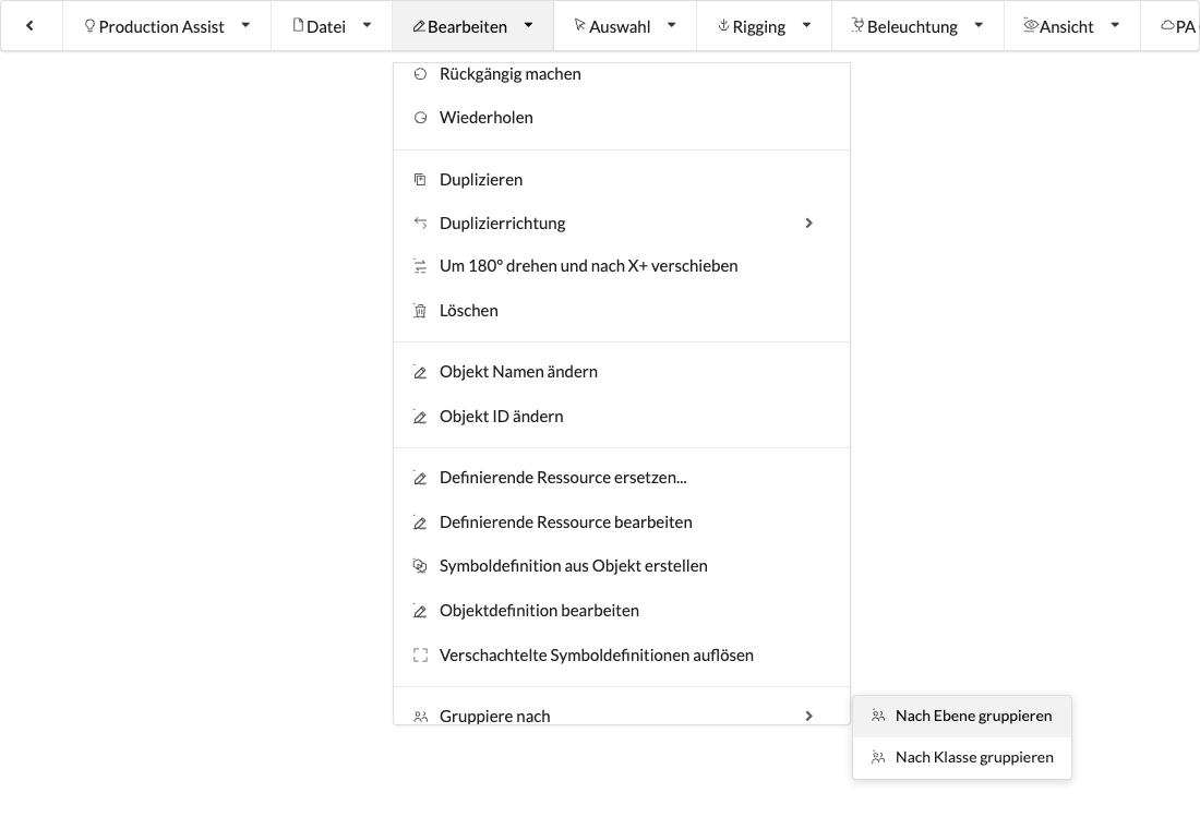
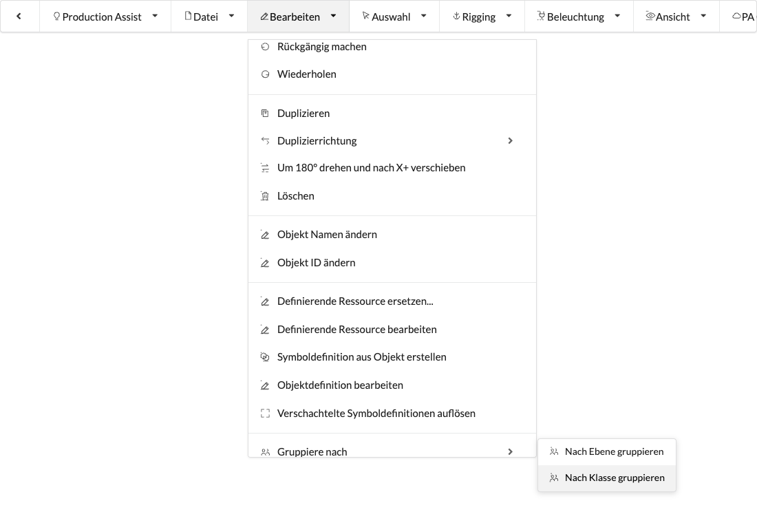
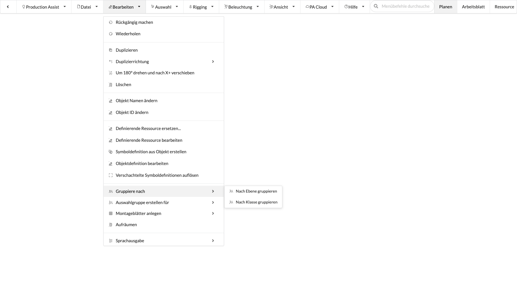
| Command | What happens | Requirement |
|---|---|---|
| Group by Layer | Creates groups in Scene Tree based on layers. | Existing objects assigned to layers. |
| Group by Class | Creates groups in Scene Tree based on classes. | Existing objects assigned to classes. |
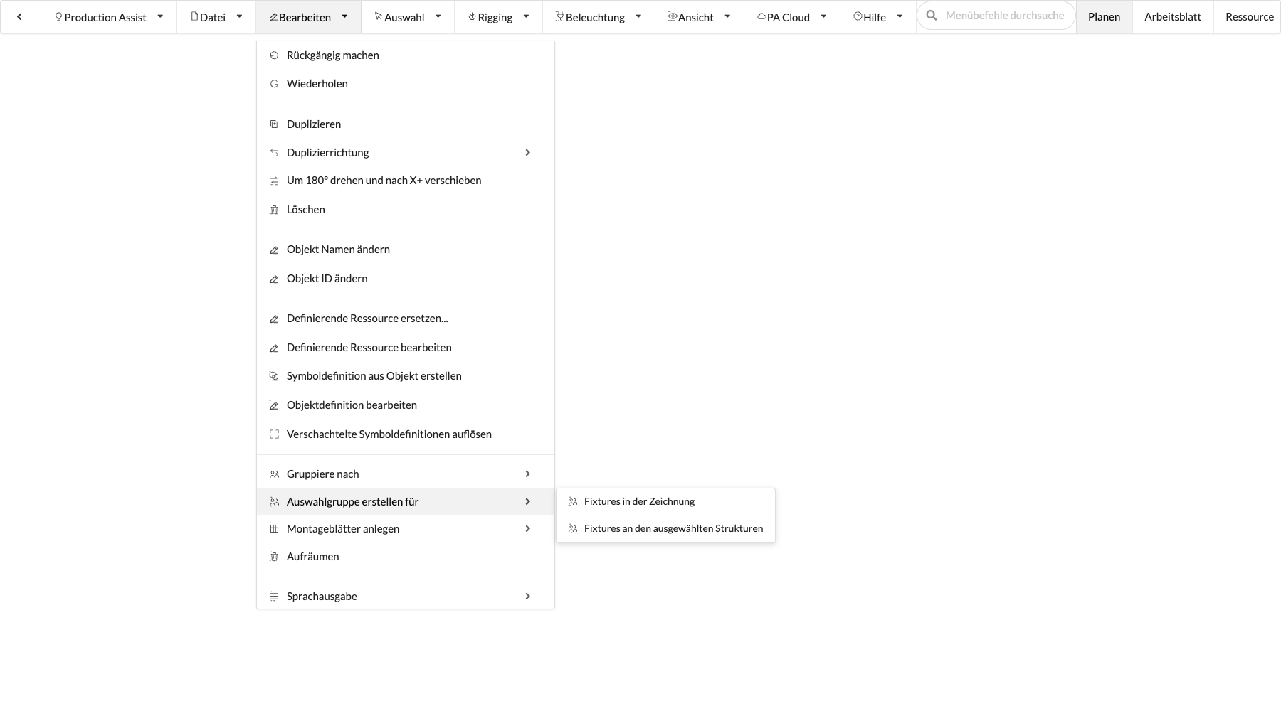
| Command | What happens | Requirement |
|---|---|---|
| Fixtures in the drawing | Automatically creates selection groups for all, odd, and even positions for each structure and fixture type. | Drawing with structures and fixtures placed on them. |
| Fixtures on the selected structures | Creates the same selection groups only for fixtures on the selected structures and their substructures. | At least one selected structure with fixtures placed on it. |
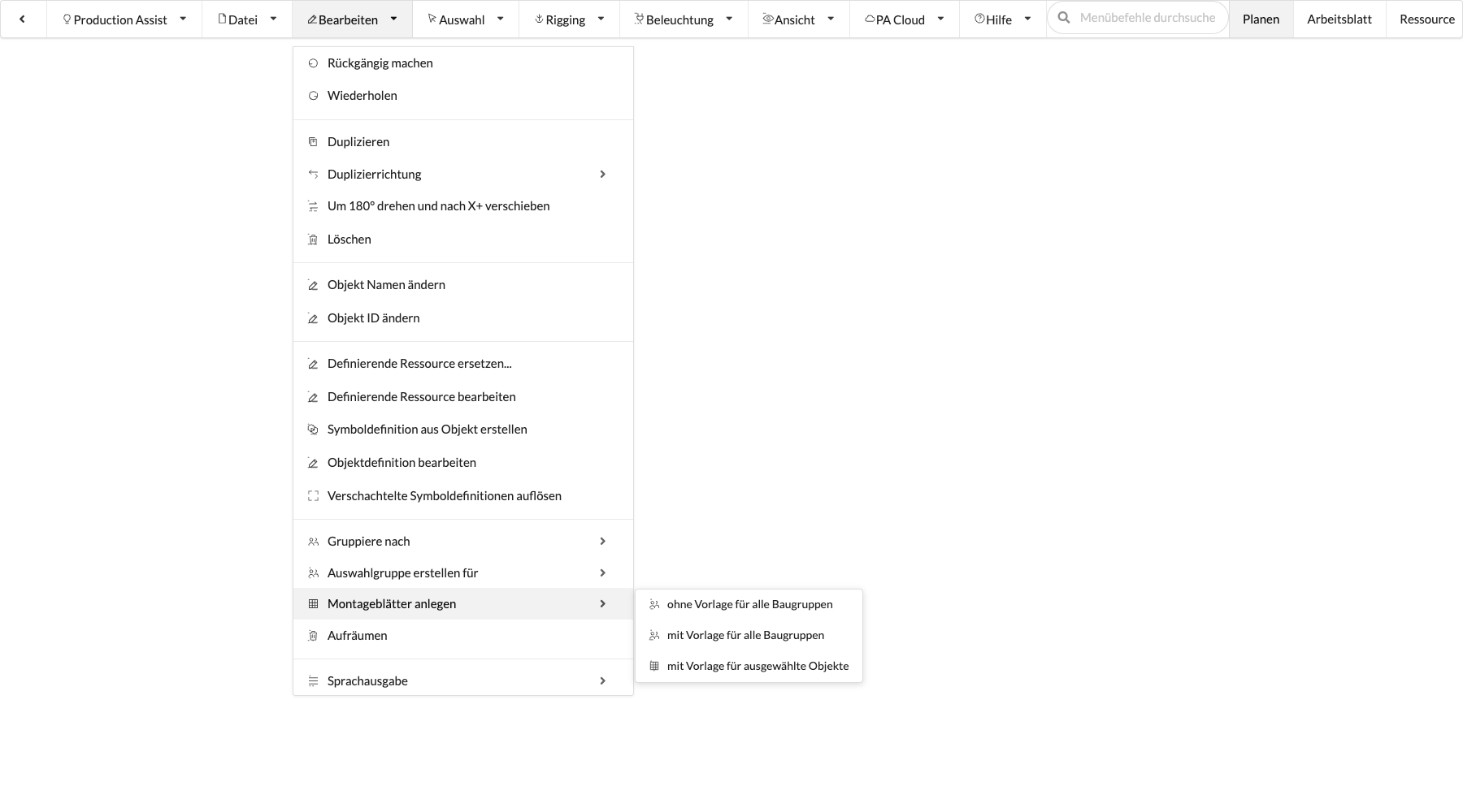
| Command | What happens | Requirement |
|---|---|---|
| without template for all assemblies | Creates empty Assembly Sheets for all groups. | Existing assemblies. |
| with template for all assemblies | Creates Assembly Sheets for all groups based on a template. | Existing assemblies and at least one matching template. |
| with template for selected objects | Creates Assembly Sheets from the current selection using a template. | Suitable selection and at least one matching template. |
In the Selection menu, you control object selection, create subsequent objects, and run commands directly on selected elements.
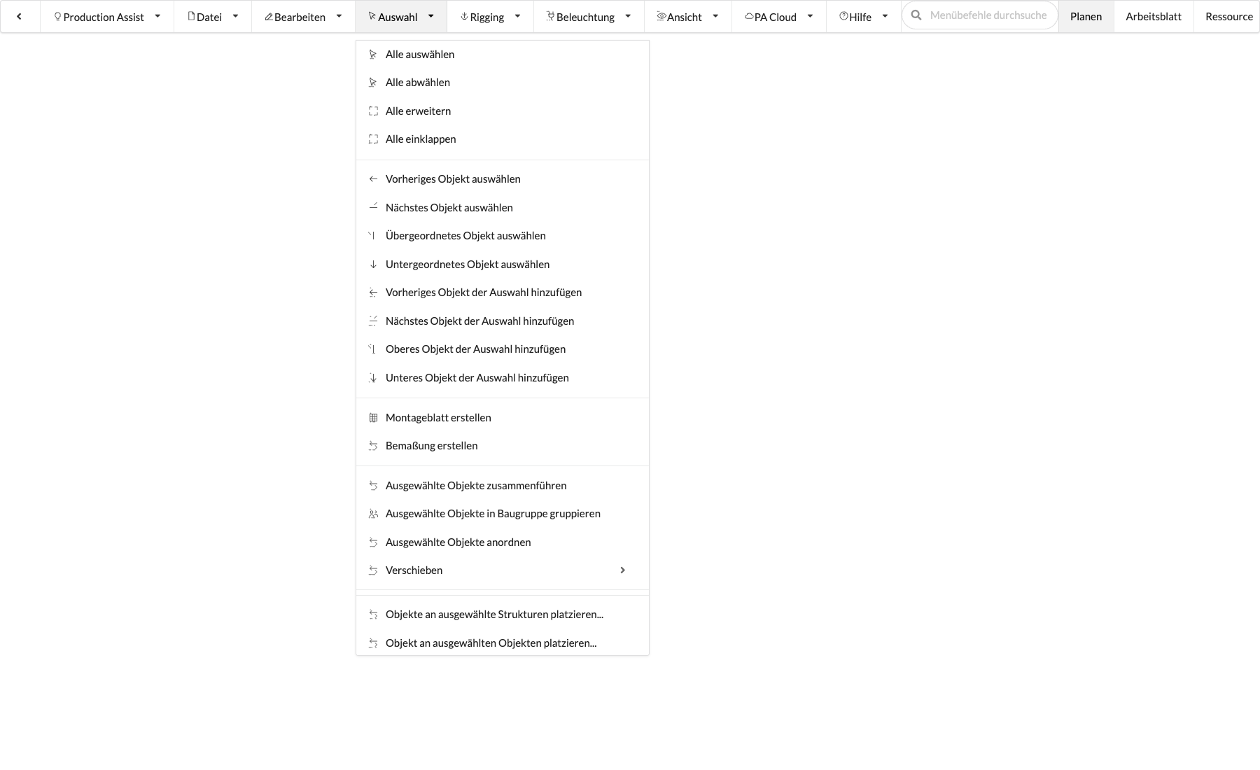
| Command | What happens | Requirement |
|---|---|---|
| Select All | Selects all objects that can be visible in Scene Tree. Objects hidden there are skipped. | Open drawing. |
| Deselect All | Clears the current object selection. | Open drawing. |
| Expand All | Expands the entries in Scene Tree. | Open drawing. |
| Collapse All | Collapses the entries in Scene Tree. | Open drawing. |
| Select Previous Object | Selects the previous object in the hierarchy. If there is no previous object at the same level, the selection moves to the parent object. | An object selected in Scene Tree. |
| Select Next Object | Selects the next object in the hierarchy. If there is no next object at the same level, the selection moves to the next object at the parent group's level. | An object selected in Scene Tree. |
| Select Parent Object | Moves from a selected child object to its parent object. If there is no parent, the current object remains selected. | Selected object with a parent object. |
| Select Child Object | Moves to the first child object. If there is no child, the current object remains selected. | Selected object with child objects. |
| Add Previous Object to Selection | Adds the previous object in the hierarchy to the current selection. | An object selected in Scene Tree. |
| Add Next Object to Selection | Adds the next object in the hierarchy to the current selection. | An object selected in Scene Tree. |
| Add Parent Object to Selection | Adds the parent object to the current selection. | Selected object with a parent object. |
| Add Child Object to Selection | Adds the first child object to the current selection. | Selected object with child objects. |
The Previous Object, Next Object, Parent Object, and Child Object commands need a most recently selected single object as their starting point. Select All, Deselect All, Expand All, and Collapse All clear this starting reference. Select an object again in Scene Tree or the Renderer to start navigating. After a command with ... to Selection, check the selection in Scene Tree: with an existing multiple selection, the current handler may deselect an object instead of only extending the selection.
| Command | What happens | Requirement |
|---|---|---|
| Create Assembly Sheet | Creates a separate Assembly Sheet for each selected object. For details, see the Assembly Sheet creation tutorial. | Open drawing with selected objects. |
| Create Dimension | Creates dimensions for the selected objects. | Open drawing with selected objects. |
| Merge Selected Objects | Combines at least two selected objects in a new symbol definition and replaces the selection with the new object. | At least two objects selected; unavailable in geometry Edit Mode. |
| Group Selected Objects into Assembly | Prompts for a name and creates a new assembly (Assembly Group) from the selection. See the context menu steps. | At least two objects selected; a single object does not create an assembly. |
| Arrange Selected Objects | Rearranges the existing selection as a line, rectangle, or circle; it does not create copies. See the dialog details. | At least one selected object. |
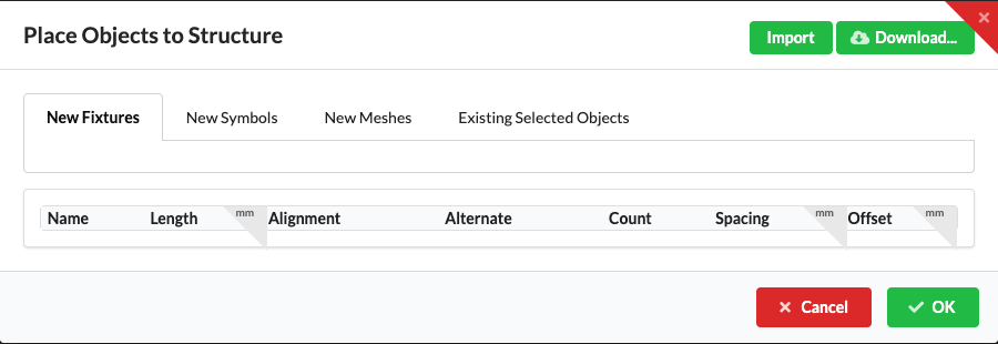
| Place Objects on Selected Structures... | Places new fixtures, symbols, or meshes along selected structural geometry. In the Existing Selected Objects tab, selected objects are instead moved onto a structure. See the guide. | Selected target structure with structural geometry. |
| Place Object on Selected Objects... | Creates an object from the selected fixture, symbol, or mesh resource at each selected target position. | At least one selected target object and a suitable resource. |
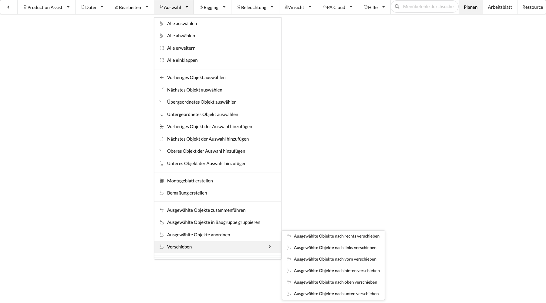
| Command | What happens | Requirement |
|---|---|---|
| Move Selected Objects to the Right | Increases the X value of the selected objects by 100 mm. | At least one selected object. |
| Move Selected Objects to the Left | Decreases the X value of the selected objects by 100 mm. | At least one selected object. |
| Move Selected Objects Forward | Increases the Y value of the selected objects by 100 mm. | At least one selected object. |
| Move Selected Objects Back | Decreases the Y value of the selected objects by 100 mm. | At least one selected object. |
| Move Selected Objects Up | Increases the Z value of the selected objects by 100 mm. | At least one selected object. |
| Move Selected Objects Down | Decreases the Z value of the selected objects by 100 mm. | At least one selected object. |
The Rigging menu contains structural calculations, structural tools, and commands for rigging hardware, loads, and checks. The basics and complete workflow are described under Structural Calculations.
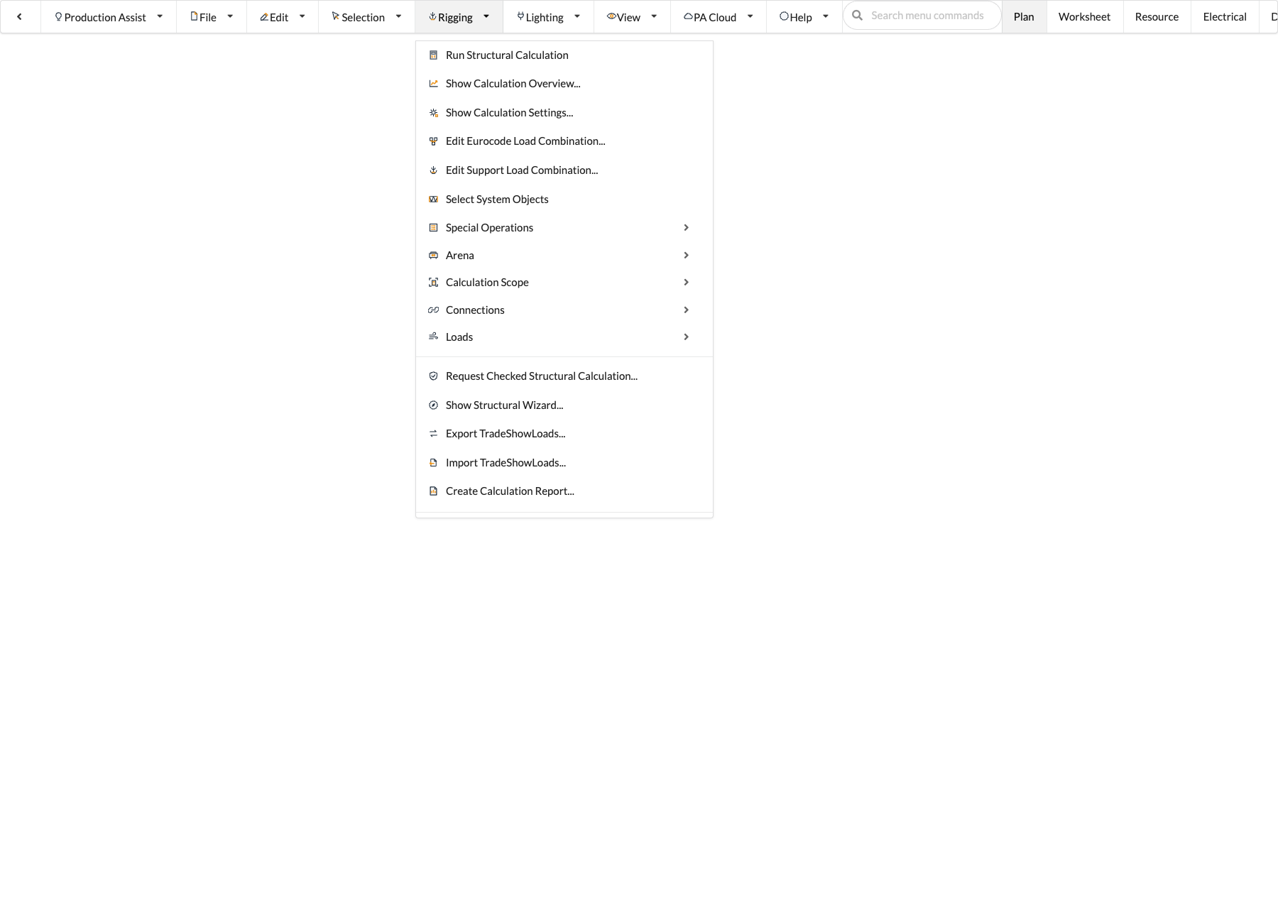
| Command | What happens | Requirement |
|---|---|---|
| Read and calculate... | Reads the current Vectorworks drawing again and then starts the structural calculation. | Only in the Vectorworks integration with an open host drawing. |
| Calculate statics | Starts a new structural calculation for the current drawing or selected calculation scope. It can also be started manually when real-time calculation is disabled, which is useful for explicitly triggering a recalculation. | Open drawing with structurally relevant objects. |
| Show calculation overview... | Opens the overview with calculation status, errors, loads, wind loads, and result groups. See Calculation Overview for instructions. | Open drawing. |
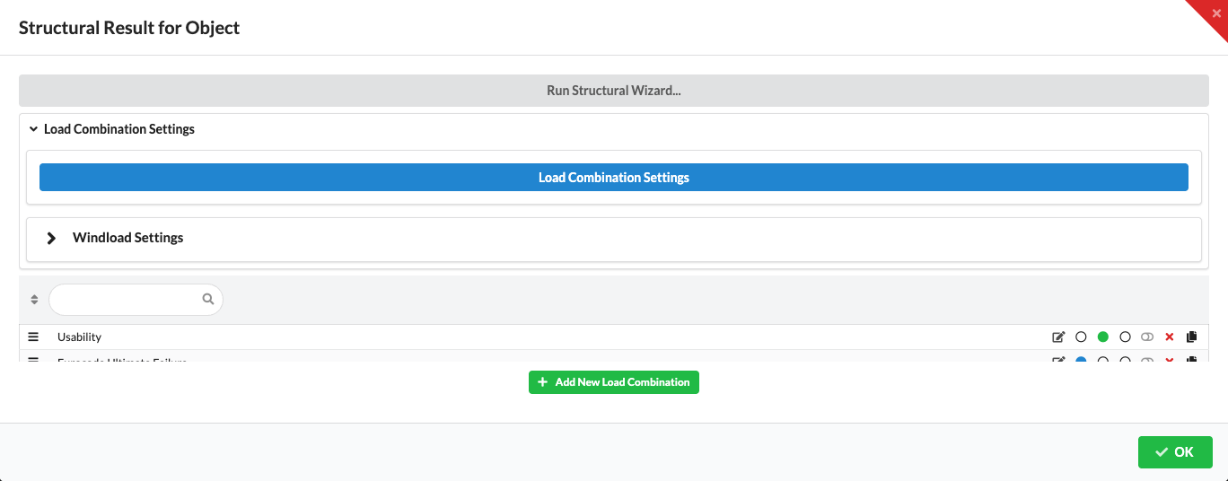
| Show calculation settings... | Opens the settings dialog for the structural calculation. You can adjust parameters such as wind loads, safety factors, load combinations, and other calculation parameters. The same dialog is also available through Calculation Navigation (for example, Load Combinations); this menu command opens it directly. | Open drawing. |
| Edit Eurocode Load Combination... | Opens the edit dialog in Calculation Navigation for the load combination currently active for the general rigging calculation. | Open drawing with an active load combination for the general calculation. |
| Edit Support Load Combination... | Opens the edit dialog in Calculation Navigation for the load combination currently active for supports. | Open drawing with an active support load combination. |
| Select system objects | Selects the structural system of the first selected structural object, support, or related load. The current selection is replaced. This includes connected structural members, supports, and point and line loads. | An object in a calculable system is selected. |
| Request verified structural calculation... | Opens the order dialog for an external review. Check the price and project details; the order is submitted only when you select Buy verified structural calculation. See the Guide to requesting a verified structural calculation for details. | Signed-in account with access to a project linked to a PA Cloud project and workspace; an available billing/reporting account is also required to place an order. |
| Show Structure Wizard ... | Opens the Structure Wizard to select presets for wind and area loads, ballast, and floor loads. The selections for area loads, ballast, and floor loads are not reliably applied; after selecting OK, check the affected object and load-combination settings. The wind-load selection is set in the load-combination settings. | Open drawing. |
| Export TradeShowLoads... | Opens the fields for the exhibition, hall, booth, and company. Production Assist then calculates the drawing and saves the load overview and support points for motors and bridles, together with this exhibition information, in a .tsle file. See the TradeShowLoads guide for details. | Drawing with calculable loads and supports. |
| Import TradeShowLoads... | Displays the data in a .tsle file for review and creates new objects from its points. Existing load objects are not reconciled or overwritten. See the TradeShowLoads guide for details. | Existing .tsle file. |
| Export calculation report as PDF... | Exports the structural calculation results as a report. | Existing calculation results. |
Show calculation settings... opens the full-screen Structural Results for Object dialog. There, you can open the Structure Wizard, show the Load Combination Settings and Wind Load Settings sections, and manage load combinations. Select OK to close the dialog. The example shows expanded load combination settings with synthetic sample data.
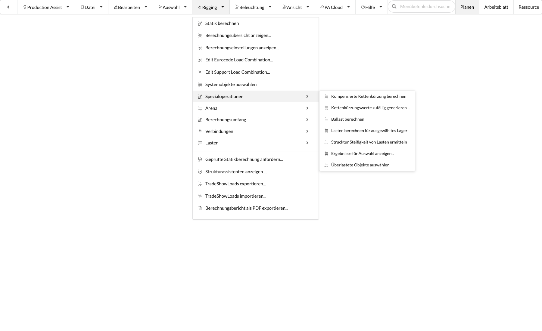
| Command | What happens | Requirement |
|---|---|---|
| Calculate compensated chain shortening | Calculates and applies chain shortening values to suitable supports to compensate for the system's vertical deformation. Individual supports can be excluded from compensation. You can also enable automatic application after a structural calculation in the calculation settings. | Drawing with calculable structures and suitable supports. |
| Generate chain shortening values randomly... | Assigns a random value between the minimum and maximum to the Chain Shorten property of all supports belonging to the selected objects. With no selection, values are reset for all objects in the drawing; existing chain shortening values are overwritten. Choose a minimum that is not greater than the maximum; the dialog does not prevent an invalid order. | Drawing; select the relevant objects to target a specific change. |
| Calculate ballast | Calculates the ballast required for Ground Support supports using the active load combination for tipping. Production Assist checks several wind directions, also uses the second wind pressure setting if enabled, and takes the specified friction value into account if floor friction is enabled. The greatest calculated requirement is applied to each support in the drawing. See the Guide to calculating and checking ballast for requirements and result labels. | Drawing with calculable Ground Support supports. |
| Reset Ballast for Auto-generated Supports | Resets the stored ballast of all automatically generated ground supports throughout the drawing to zero. No selection is required. Supports, geometry, and weights of manually placed Ground Support Attachments remain unchanged. The command can be undone; check the recalculated results afterward. See Reset ballast. | Open drawing; stored ballast on automatically generated ground supports. |
| Calculate loads for selected support | Select exactly one chain hoist. For each load, the calculation determines its share and force at this support, writes both values to the load object's Object Properties, and selects load objects above the configured tolerance. If several objects are selected, only the first is considered; the command uses its first support. | Calculable drawing and a selected chain hoist with at least one support. |
| Show results for selection... | Displays diagrams of the calculated section-reaction and deformation curves for selected structural members with calculation results. A message appears if the selection is empty or no results are available. | At least one selected structural member with calculation results. |
| Select overloaded objects | Selects objects identified as overloaded in the influence-line results. The current selection is replaced. | Existing influence-line results. |
| Determine structural stiffness of loads | For point loads, calculates the additional deformation at the load point when its load factor is doubled and writes the value to Structural Stiffness on the load objects. The result is not a general stiffness measure for all load types. | Calculable drawing with point loads. |
The current German label contains a spelling mistake in the word “Struktur”. The English source name is Calculate Stiffness values for loads.
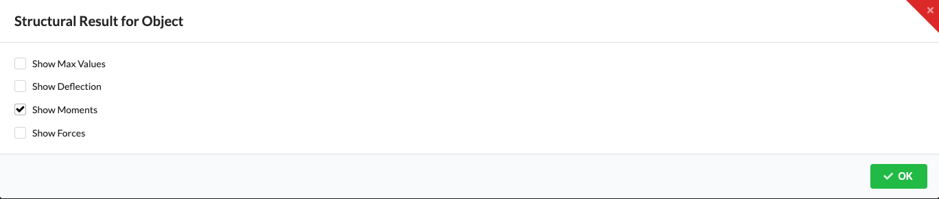
The checkboxes show or hide the corresponding diagrams directly. Show Moments is enabled when the dialog opens; Show Deformation and Show Forces are initially disabled. Show Maximum Values adds existing positive limits as comparison lines. The diagrams show the selected structural members along their length. The length, force, and moment units follow the drawing settings. The X, Y, and Z curves are red, green, and blue. Select OK to close the view.
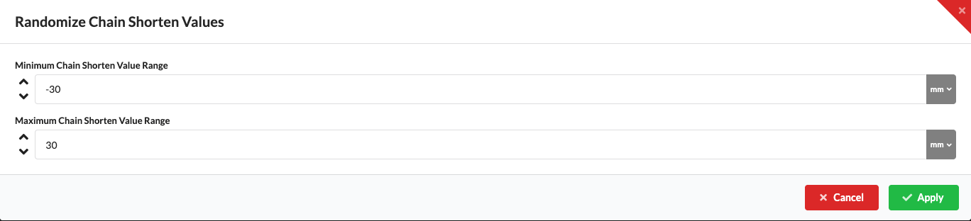
Open Rigging → Special Operations → Generate chain shortening values randomly.... The dialog initially sets a minimum of −30 mm and a maximum of +30 mm. Enter a valid range where the minimum is not greater than the maximum, then select Apply. Production Assist assigns new random values to supports belonging to the selected objects. With no selection, the command affects all objects in the drawing. Existing chain shortening values are overwritten, so check the selection before opening the dialog.
| Field / button | Effect and limitation |
|---|---|
| Minimum chain shortening value range | Lower limit for the random chain shortening values. The initial value is −30 mm; the unit shown in the field applies. |
| Maximum chain shortening value range | Upper limit for the random chain shortening values. The initial value is +30 mm. Ensure that this value is at least as large as the minimum; the dialog does not check the order. |
| Apply | Assigns new random values to the support properties of the selected objects. If nothing is selected, all objects in the drawing are included. Existing chain shortening values are overwritten. |
Important: Cancel, the close icon, and Escape also apply the entered limits and assign new random values. There is no way to close the dialog without making a change.
| Command | What happens | Requirement |
|---|---|---|
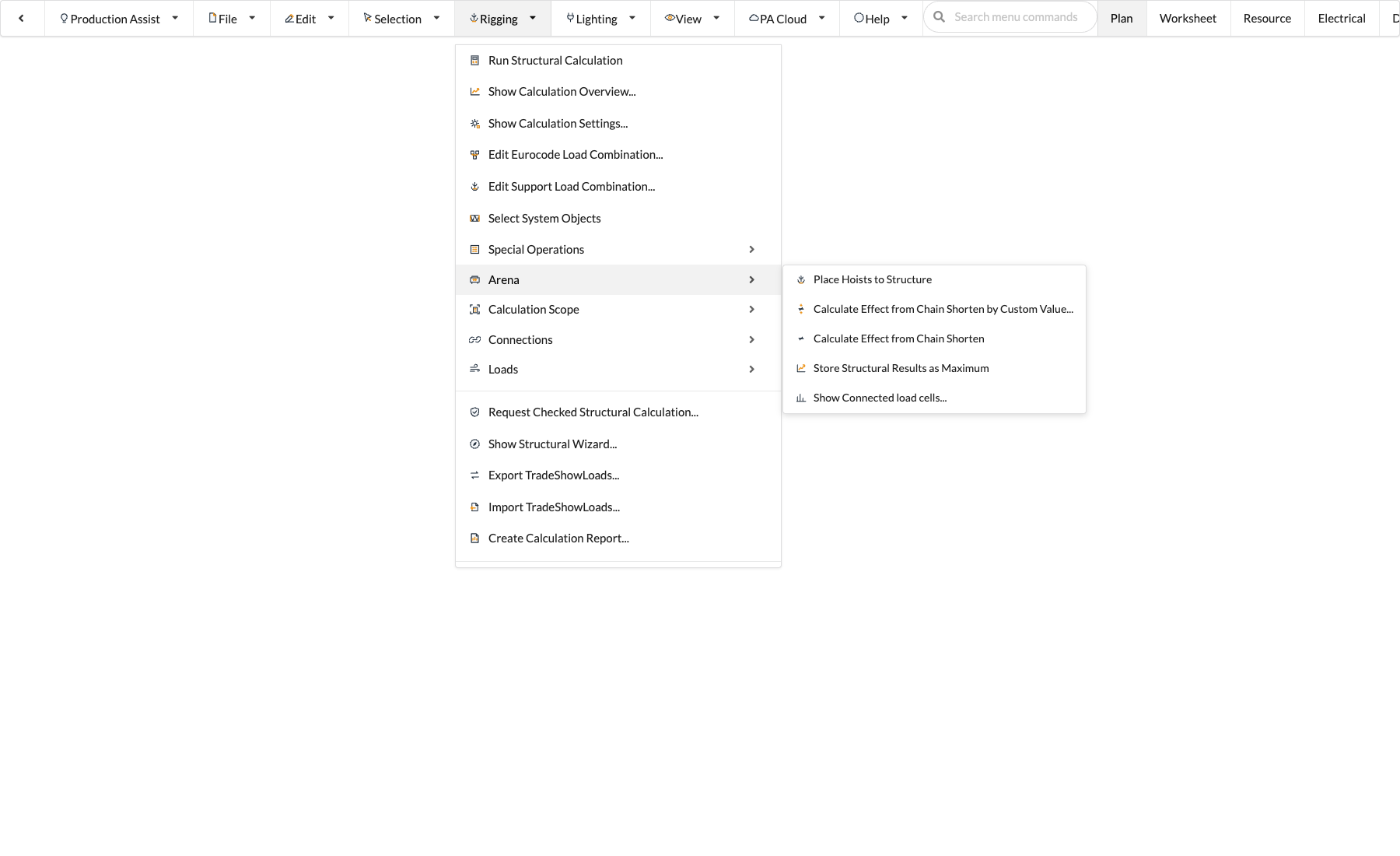
| Place hoists on structure | Opens Calculate Support Positions. Enter Max. Force in Roof and select OK. Production Assist finds suitable positions on the selected structure and creates single-leg support connections there; it does not insert hoist symbols. A structure is eligible only if Use for AI Placement is enabled. Pipes can also be included or excluded using File → Settings... → App → Use Pipes for AI Hoist Placement. Check the generated connections and their calculation results. | Selected, calculable structural members with suitable positions. |
| Calculate chain shortening effect with value... | Opens a field for an additional chain shortening in millimeters and calculates its effects for the individual lower rope supports. It compares, among other things, the support force and the highest structural utilization; the values are stored in the support properties of the affected objects. The input does not change the drawn position. | Calculable drawing with lower rope supports and the Arena plan. |
| Calculate chain shortening effect | Performs the same analysis using the default value 30 mm, without opening the delta dialog. Results are stored in the support properties of affected objects. | Calculable drawing with lower rope supports and the Arena plan. |
| Save statics results as maximum | Opens the selection for deformation, section forces, and support reactions, including limits. After OK, Production Assist calculates the system and saves the selected values in the structural members; no values are applied if the calculation fails. Check saved values in Edit Mode: Mt and Mby may currently be saved incompletely. See Process and limitations. | Drawing with calculable structural members. |
| Show connected load cells... | Opens Connect Load Cells. There, you can connect Broadweigh, Flexa IOT, Show Distribution, RON Stage, or T24 USB and start or stop monitoring. Inputs vary by measurement system; the Update Rate (ms) column sets the polling interval. See Connect load cells and check measurements. | Open drawing; a connected and assigned measurement system is required to retrieve measurements. |
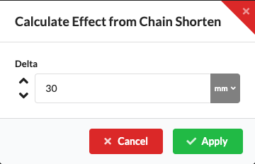
Open Rigging → Arena → Calculate chain shortening effect with value.... The dialog starts with a Delta of 30 mm. Change the value if needed and select Apply to calculate the effects for the lower rope supports in the Arena plan. Production Assist stores the comparison values in the support properties of affected objects; the drawn position does not change. A calculable drawing and lower rope supports in the Arena plan are required.
| Field / button | Effect and limitation |
|---|---|
| Delta | Additional chain shortening for the analysis. The initial value is 30 mm; the displayed unit follows the configured unit. |
| Apply | Starts the analysis using the entered delta and writes the comparison values to the support properties of affected objects. |
Important: Cancel, the close icon, and Escape also start the calculation using the entered delta. There is no way to close the dialog without calculating.
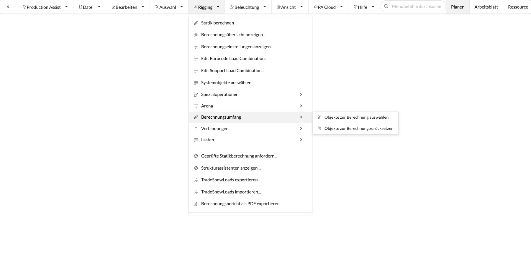
The following commands set the scope of the structural calculation. Select objects for calculation replaces the previous scope with the current selection; scoped objects appear in red in the Scene Tree. Suitable child objects are also included when assemblies are selected. Reset objects for calculation clears the defined scope and the current object selection. While a fixed scope is active, you can also reset it using the red, blinking Reset calculation scope button above the Scene Tree. The regular calculation scope then applies again, subject to other calculation settings. These commands do not delete saved result values. You can also set a selection group as the scope using its calculator icon.
| Command | What happens | Requirement |
|---|---|---|
| Select objects for calculation | Replaces the previous calculation scope with the current object selection. | Selected objects or assemblies. |
| Reset objects for calculation | Clears the defined calculation scope and current object selection; you do not need to select the affected objects again. | Open drawing. |
| Command | What happens | Requirement |
|---|---|---|
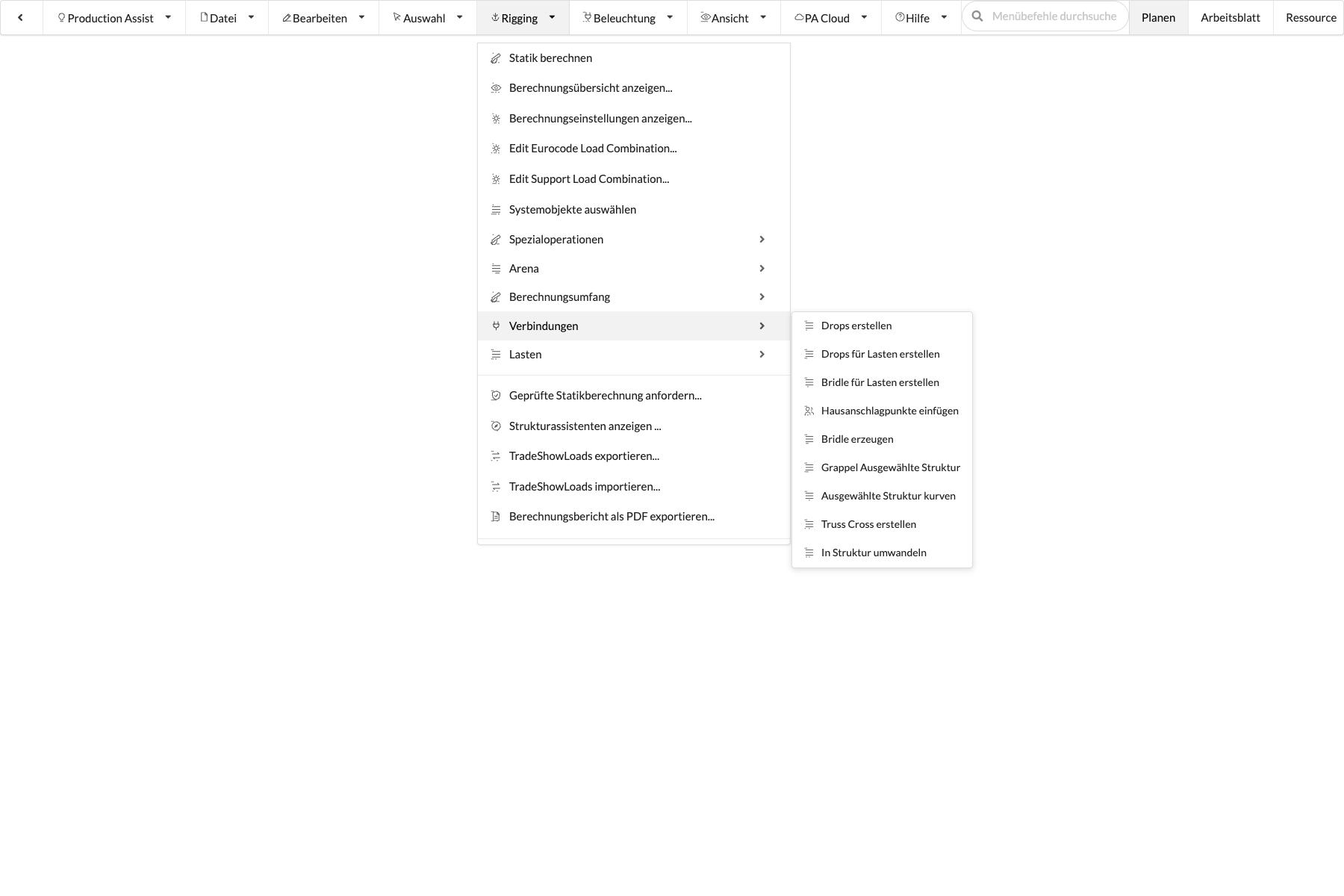
| Create Drops | Opens Place Objects on Structure, where you select a symbol for new Drops. Production Assist creates Drops at intersections of structural members from different objects when their heights at the intersection differ by more than 100 mm. Existing Drops at the same points are skipped. See Insert connections for creation and checking. | At least two selected structural objects with intersecting members. |
| Create Drops for Loads | For each selected load object, finds the nearest structural member in plan view and creates a single-leg connection from the load point to the member. No settings dialog opens. | Selected load objects used as loads; structural members in the drawing. |
| Create Bridle for Loads | For each selected load object, finds the nearest structural member in plan view and creates a two-leg connection from the load point to both ends of the member. No settings dialog opens. | Selected load objects used as loads; structural members in the drawing. |
| Insert house anchor points | Adds a House Rigging Point at the start point of an existing rope support if one is not already assigned. No dialog for capacity or orientation opens. Check the added objects before calculating. | Drawing with suitable structures and rope support connections. |
| Generate Bridle | Creates a two-leg connection with a Drop to two suitable adjacent structural members for selected supports, loads, and regular objects. For objects without supports, the load position, including the load offset, is used; Use as Load does not need to be enabled. Structural members and parent assemblies are not additionally used as load points. No settings dialog opens. Check the generated connections in the model and calculation afterward. | Selected supports, loads, or regular objects, and two suitable reachable structural members above the target point. |
| Extend Selected Structure at Right-Angle Intersections | Checks selected structures for perpendicular intersections. If a member end is within half a profile width of the other structure, the command enables structural extension at that point and sets its offset. It does not insert a bolted connection or open a capacity dialog. | Selected structural members with suitable perpendicular geometry. |
| Curve selected structure | Checks intersections of selected structures and sets the structural-extension offset at the nearest member ends. It does not create curved segments or open a settings dialog. Check the changed objects in Object Properties afterward. | Selected structural members whose axes intersect outside the member segments. |
| Create Truss Cross | Creates Truss Crosses at detected intersections of selected structural members when there is a height difference. Check the connection and its Truss Cross Type in the model and calculation; see Insert connections and Create and check Truss Crosses. | Selected structural members with suitable intersections and a height difference. |
| Convert to structure | Converts selected objects to structural objects. Lines belonging to an object are automatically converted to structural members. This is useful when structural members already exist, for example after an import, and you want to quickly turn lines into load-bearing structural parts. | Suitable objects or selected lines. |
| Command | What happens | Requirement |
|---|---|---|
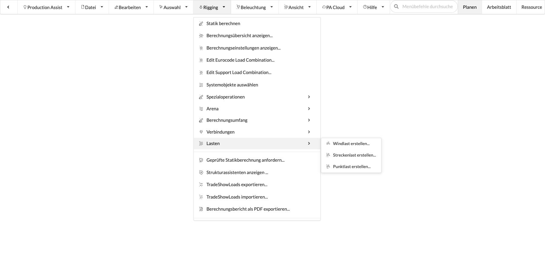
| Create wind load... | Opens Add Wind Load. Set wind load per length below and above the global Z height First Height, and set the force angle in the horizontal plane. For a structural member that crosses this height, Production Assist splits the load at the intersection; the two values are not interpolated between. Ropes, rope extensions, and Truss Crosses are skipped. See Understand and check wind loads for other dialog fields and checking generated loads. | Select suitable structural objects. |
| Create line load... | Opens Add New Line Load and creates a uniform line load over the full length of every suitable selected member. X/Y/Z are force components per unit length; the entered values apply to each member and are not distributed across the selection. Use Define Load in GCS to switch between global and local axes. Ropes, rope extensions, and Truss Crosses are skipped. | Select suitable structural objects. |
| Create point load... | Opens Insert Point Load and creates a point load on every suitable selected member using the entered X/Y/Z force components. By Height uses the intersection of a global horizontal plane with the straight extension of the member axis; the point does not have to be between the member ends. Horizontal members are skipped in this mode. By Percentage sets the position within each individual member. Use Define Load in GCS to choose global or local axes. Ropes, rope extensions, and Truss Crosses are skipped. There is no preview; check the number and positions of the loads after creation. | Select suitable structural objects. |
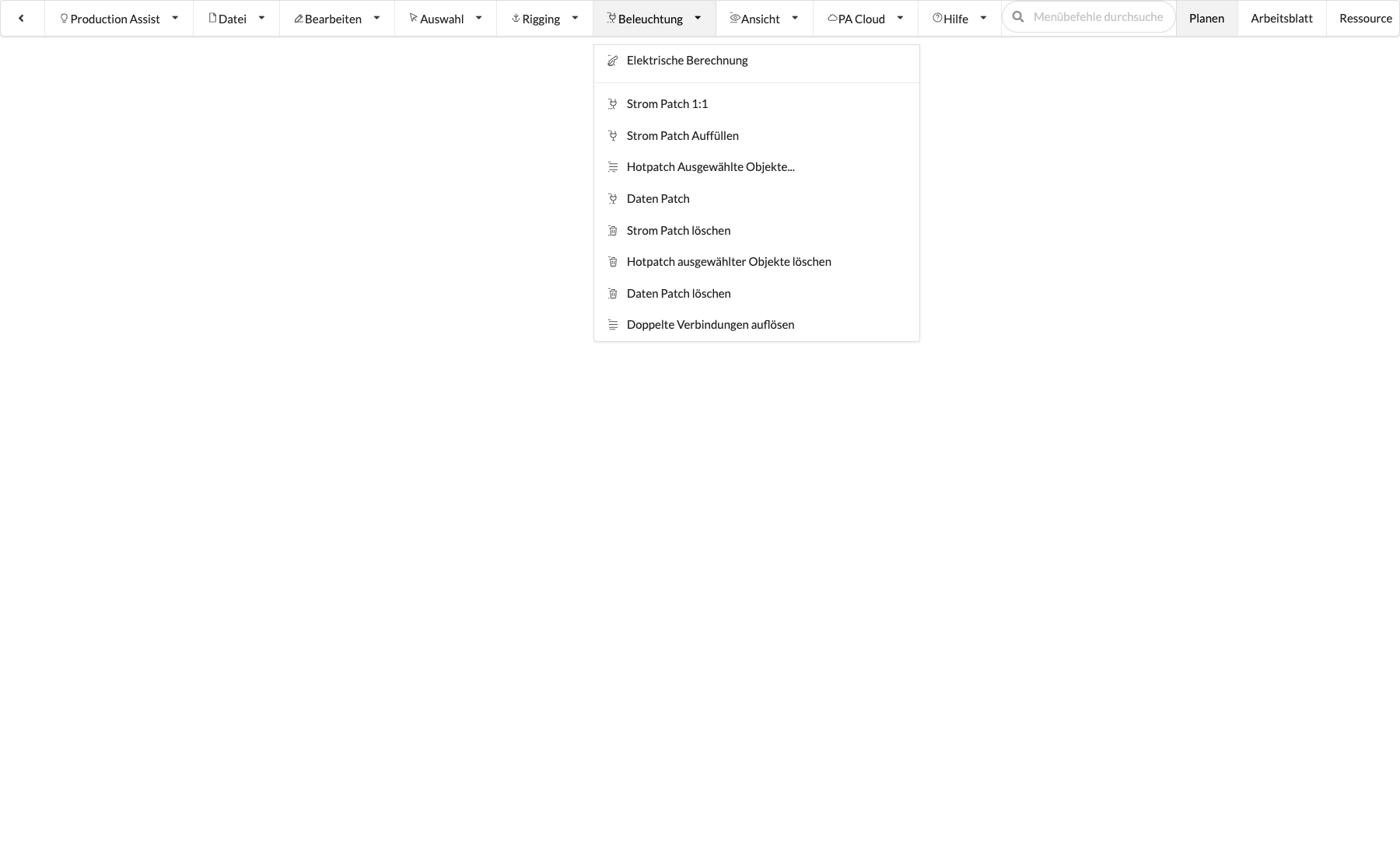
In the Lighting menu, you manage power and data connections for fixtures and other consumers.
The menu also contains online commands that are listed under PA Cloud as well: View project calendar, Commit changes for resource, Download all online resources, Add user to project, Share project link…, Connect to PA-NET, and Log out. Their requirements and operation are described under PA Cloud.
For setting up, checking, and ordering electrical connections, see Electrical Planning. Electrical View explains how patch results are displayed.
| Command | What happens | Requirement |
|---|---|---|
| Electrical calculation | Runs the electrical calculation again and updates the displayed electrical results. Use this command when you want to trigger an immediate recalculation after making changes. | Open drawing with electrical connections. |
| Power Patch 1:1 | Connects free power inputs on the selected consumers to compatible free outputs on the selected distributors. Inputs that are already connected are skipped. The order is determined by Patch Tool Order in Electrical Settings; consumers remain unchanged if their connections are incompatible or no free outputs are available. | Selection of consumers and distributors with compatible power connections. |
| Power Patch Fill | Assigns additional selected consumers to compatible outputs on the selected distributors. The Auto-Patch Mode, Auto-Patch Fill – Leave Percentage Free, and Auto-Patch Fill – Leave Wattage Free settings affect the power reserve taken into account. After running the command, check the connections and utilization in Object Properties. | Selection of consumers and distributors with compatible power connections. |
| Hotpatch Selected Objects... | Opens the Hotpatch matrix for the selected devices. Click a cell to set or remove an assignment; the change is applied immediately. The matrix shows power values and utilization. OK closes the dialog. Check the assignments before closing; see Hotpatch in Object Properties for more information. | Selected devices with compatible Hotpatch inputs and outputs. |
| Data Patch | Connects compatible, free data inputs and outputs on the selected objects. Patch Tool Order determines the order of processing; a connection for every selected device is not guaranteed. | Selection of objects with compatible data connections. |
| Delete Power Patch | Removes power connections from the selected objects. Then check the affected inputs and outputs in Object Properties. | Selection with existing power connections. |
| Delete Hotpatch for Selected Objects | Removes Hotpatch connections from the selected objects. A previous 1:1 assignment is not restored automatically. | Selection with existing Hotpatch connections. |
| Delete Data Patch | Removes data connections from the selected objects. Then check the affected inputs and outputs in Object Properties. | Selection with existing data connections. |
| Resolve Duplicate Connections | The menu item is visible, but with the menu parameters currently passed it does not resolve any connections. Check outputs with multiple assignments in Object Properties and correct the connections there. | Drawing with outputs assigned more than once. |
In the View menu, you control the display in the Renderer and show or hide work areas.
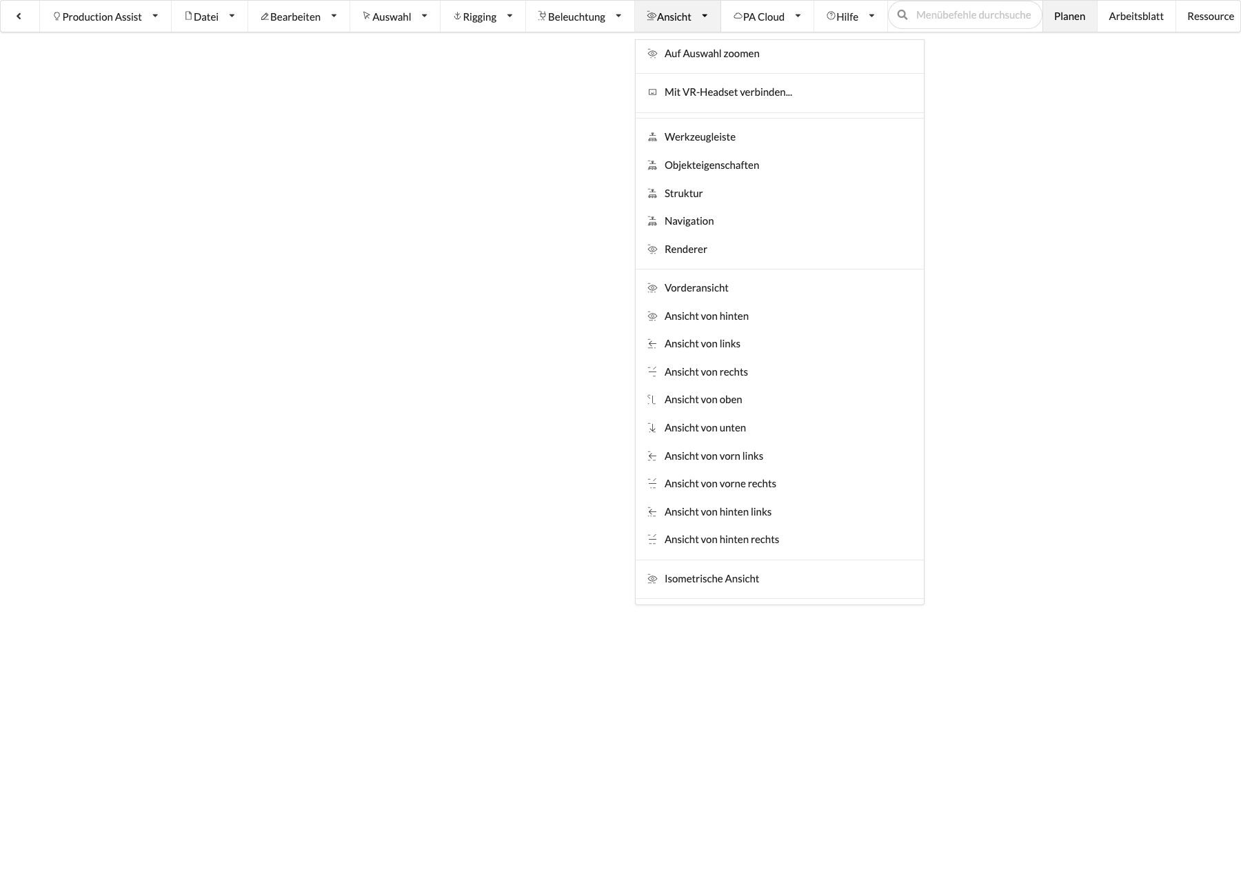
| Command | What happens | Requirement |
|---|---|---|
| Reset Zoom | Resets the window's UI zoom level to its default. This resets the scaling of the user interface (font sizes, icons, and layout). The effect is complete in the desktop/Electron app and depends on the host in embedded browsers or plugins. | Supported desktop or Electron view; in plugins, depends on the browser host. |
| Zoom In | Increases the UI zoom level (font sizes, icons, and UI elements appear larger), which can improve readability. It works in the desktop/Electron app; support in embedded browsers or plugins depends on the host. | Supported desktop or Electron view; in plugins, depends on the browser host. |
| Zoom Out | Decreases the UI zoom level (font sizes, icons, and UI elements appear smaller) to show more content. It works in the desktop/Electron app; support in embedded browsers or plugins depends on the host. | Supported desktop or Electron view; in plugins, depends on the browser host. |
| Toggle Full Screen | Switches the active application window between windowed and full-screen display. | Desktop app or host that supports the full-screen command. |
| Zoom to Selection | Fits the 2D and 3D views to the current selection. If nothing is selected in the 2D view, all visible objects are fitted; in edit mode, this applies to the content being edited. In integrations that provide their own 2D drawing view, that view remains active; in other views, the application switches to the 3D view when needed. The F key runs the same command. | Displayable objects; no selection is required in 2D. |
| Connect to VR Headset... | Opens the About Production Assist dialog with a QR code, local address, and instructions for the VR connection. Scan the QR code with the headset or open the displayed address in the headset browser. HTTPS is required for online projects. For a local HTTP connection, you must add the computer's IP address to Chrome once as a secure origin; the dialog shows chrome://flags/#unsafely-treat-insecure-origin-as-secure. Use this setting only on a local network, not with a public IP address. For details, see Local VR connection from the desktop app. | Production Assist and headset on a reachable local network; Chrome with the setting described in the dialog, followed by a restart. |
These commands control the visibility of Production Assist's individual UI areas. For example, you can show or hide the toolbar, Object Properties, the structure, Navigation, or the Renderer. Areas you show appear in the saved layout. This lets you reopen an area you closed by accident or adjust the layout.
| Command | What happens | Requirement |
|---|---|---|
| Toolbar | Shows or hides the toolbar. | Open drawing. |
| Object Properties | Shows or hides Object Properties. | Open drawing. |
| Structure | Shows or hides the Scene Tree. | Open drawing. |
| Navigation | Shows or hides the Navigation area. | Open drawing. |
| Renderer | Shows or hides the Renderer area. | Open drawing. |
The standard views point the 3D camera in fixed directions. They keep the current camera distance and center the scene around its origin; a selected object is not zoomed in automatically. If an object is no longer in view, select it and use Zoom to Selection. You can also access the ten viewing directions using num0 through num9 on the numeric keypad. Isometric View switches between perspective and orthographic camera views; its default shortcut is V.
| Command | What happens | Requirement |
|---|---|---|
| Front View | Switches the Renderer to the front view. | Open drawing with a visible scene. |
| Back View | Switches the Renderer to the rear view. | Open drawing with a visible scene. |
| Left View | Switches the Renderer to the left side view. | Open drawing with a visible scene. |
| Right View | Switches the Renderer to the right side view. | Open drawing with a visible scene. |
| Top View | Switches the Renderer to the top view. | Open drawing with a visible scene. |
| Bottom View | Switches the Renderer to the bottom view. | Open drawing with a visible scene. |
| Front Left View | Sets the viewing direction diagonally from the front left. | Open drawing with a visible scene. |
| Front Right View | Sets the viewing direction diagonally from the front right. | Open drawing with a visible scene. |
| Back Left View | Sets the viewing direction diagonally from the back left. | Open drawing with a visible scene. |
| Back Right View | Sets the viewing direction diagonally from the back right. | Open drawing with a visible scene. |
| Isometric View | Switches the 3D camera between perspective and orthographic display; the setting is called Perspective Camera View. | Open drawing in the 3D view. |
| Command | What happens | Requirement |
|---|---|---|
| Reload Window | Reloads the Production Assist window. | Desktop app. |
| Open Developer Tools... | Opens the developer tools for the application window. They contain technical information for analysis and troubleshooting. | Desktop app. |
In the current menu definition, Toggle Full Screen is listed three times. As a result, the View menu may show three entries with the same name; each switches between windowed and full-screen display.
The desktop app's native Window menu displays additional work windows alongside the renderer. Electron and the operating system manage it, so it is not available as a React interface to the UI renderer; the menu bar recording does not show it. Select a window entry to show that window. If it is already the active window, the same entry hides it.
| Command | What happens | Requirement |
|---|---|---|
| Worksheets | Shows or hides the window with Worksheets and Assembly Sheets. | Desktop app with an open drawing. |
| Lighting Paperwork | Shows or hides the Lighting Paperwork window. | Desktop app with an open drawing. |
| Resource Manager | Shows or hides the Resource Manager. | Desktop app with an open drawing. |
| Wiring | Shows or hides the wiring diagram with the Power and Data tabs; see Electrical View and Network Planning. | Desktop app with an open drawing; devices in the plan are required for connections to appear. |
| Timeline | Shows or hides the Timeline window. | Desktop app with an open drawing. |
| DMX Overview | Shows or hides the DMX patch, with used and free addresses for each universe; connection wiring is under Wiring → Data. | Desktop app with an open drawing; fixtures with DMX addresses are required for patched channels. |
| Minimize | Minimizes the active window. | Desktop app. |
| Bring All to Front | Brings all Production Assist windows in front of other windows. | macOS desktop app with multiple windows open. |
The PA Cloud menu contains commands for transferring and synchronizing online projects. Multiple people can work on the same project in their own workspaces. Their changes are saved in the respective workspace and become visible in Master only after they are merged. Review differences and possible conflicts before merging. The online workflow describes the process.
The commands Unlink Project, Open Linked Project Online, Download All Online Resources, Connect to PA-NET, and Log Out are available only in the desktop app. These entries are not shown in the web app.
The recording shows an older English PA Cloud menu. The following sections describe the available commands and what they do.
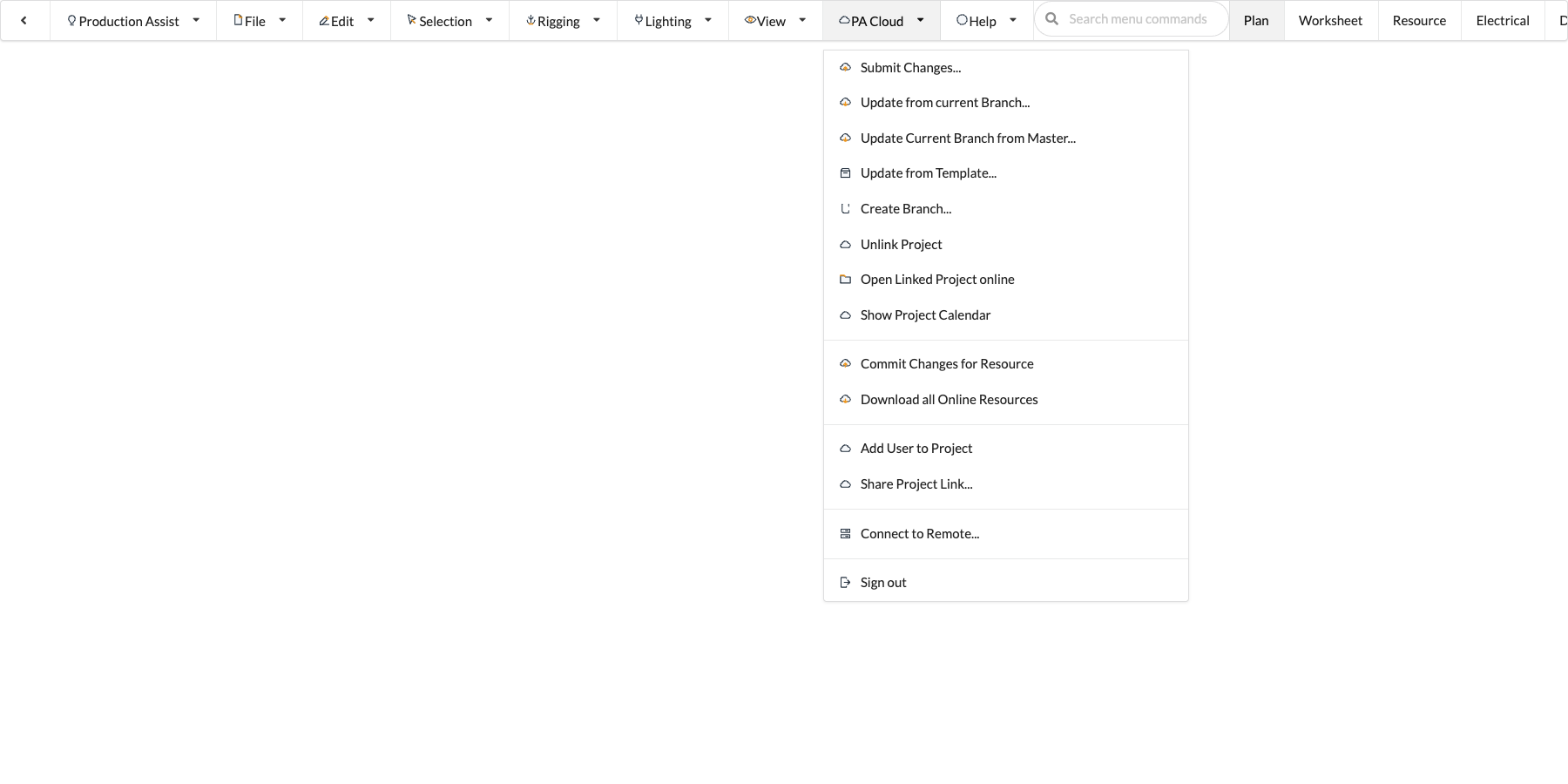
| Command | What happens | Requirement |
|---|---|---|
| Transfer Changes... | Opens the dialog for transferring local changes to the selected online workspace or creating a new project. You can select individual changes and must describe the commit. A commit to a workspace does not update Master; you must merge the workspace afterward. Uploading is also required before sending the drawing to external services (for example, a structural engineering office) for review. | Linked online project or permission to create a new project; appropriate write permissions. |
| Synchronize Workspace Changes | Synchronizes newer commits from the linked online workspace with the local drawing. Use this especially when you see the message A newer version is available on the server. Review the differences before transferring changes again. | Linked workspace and server connection. |
| Update Current Workspace from Master... | Synchronizes Master with your local drawing. Resolve any property conflicts shown in the dialog and review the result. To make it available in the online workspace, transfer the changes afterward with a commit. | Linked workspace and server connection. |
| Update from Template... | Compares the current workspace with the Master of the linked template. In the following comparison dialog, you can review the changes and select which ones to apply to the local drawing. | Workspace linked to an online project and template, and a server connection. |
| Create Workspace | Creates a new workspace based on the linked project. If the drawing is not yet linked to a project, the command first opens the Transfer Changes... dialog. | Linked online project and permission to create a workspace. |
| Unlink Project | Disconnects the local drawing from the online project; the drawing remains. Check beforehand whether you still want to transfer local changes. Without a project link, the cloud commands can no longer synchronize this workspace or provide it with new commits. You can select a project and workspace again later through Transfer Changes.... | Local drawing is linked to a project. |
| Open Linked Project Online | Opens the project page in the browser. | Linked online project. |
| View Project Calendar | Opens the project calendar for the linked project. | Online project with calendar access. |
| Transfer Changes for Resource | Transfers changes in the open resource file to the linked online project. | Open resource file with an online link and write permission. |
| Download All Online Resources | Downloads available resource files from the Production Assist server so they are available locally. The command uses the server resource list and is not tied to the currently linked project. | Internet connection and reachable Production Assist server. |
| Add User to Project | Opens the dialog for inviting additional people to the project. | Project with administration or sharing permissions. |
| Share Project Link... | Creates or displays a link for sharing the project. | Linked project and permission to share. |
| Connect to PA-NET | Opens Connect to another Production Assist App. Enter the IP address and current port of the running desktop app that should accept the connection. That app then asks whether it should send its drawing or request the drawing from the connecting app. The received drawing opens as a new active drawing. Details are in PA-NET connections. | A running desktop app reachable as the other endpoint; its IP address and current port. |
| Log Out | Signs you out of your Production Assist account. | Signed-in user account. |
The Help menu contains support, information, and installation commands.
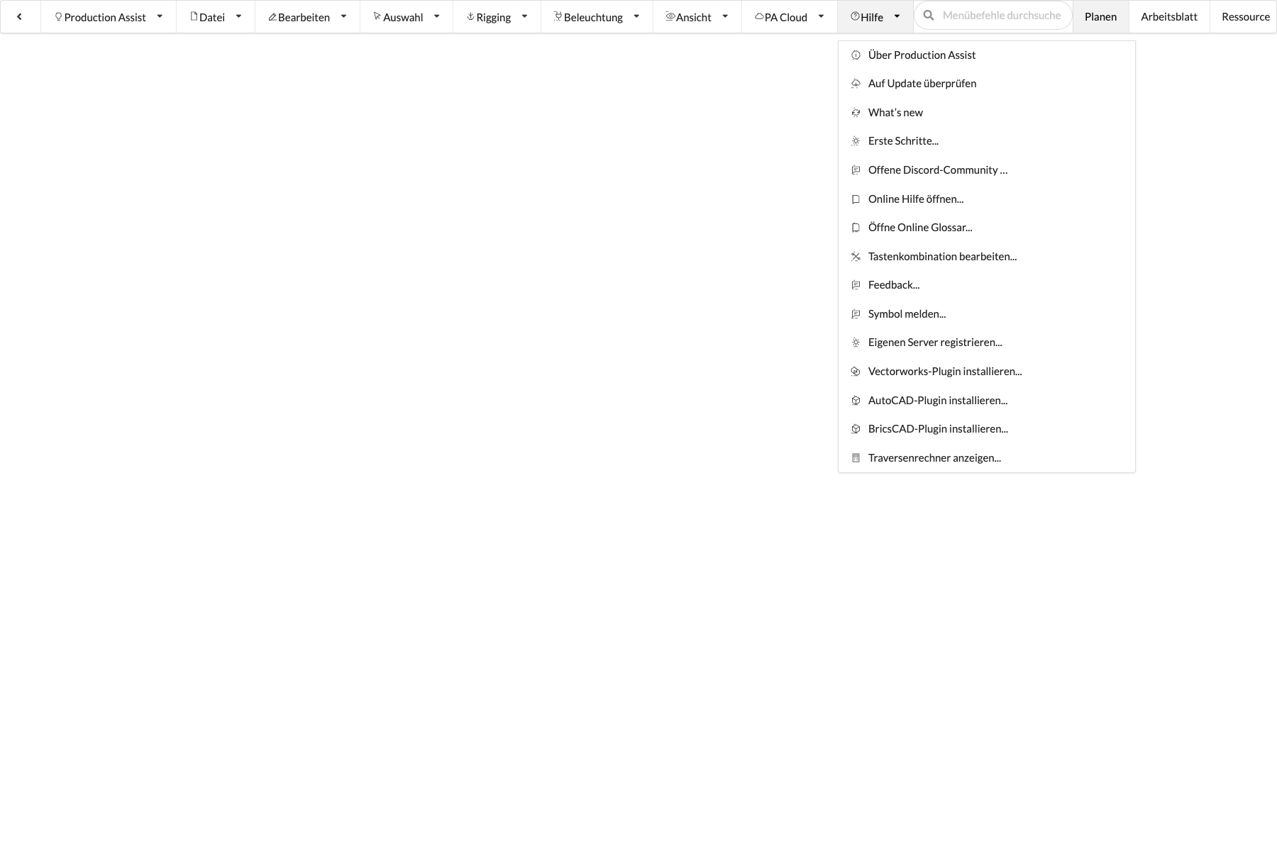
| Command | What happens | Requirement |
|---|---|---|
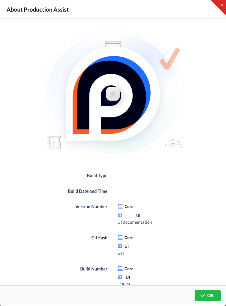
| About Production Assist | Opens the About Production Assist dialog with the build type, version number, Git hash, build number, and paths to the plugin DLL and web interface, if available. Core and UI are listed separately. | No special requirement. |
| Check for Updates | Checks whether a newer desktop app version is available. | Desktop app with internet access. This command is not available in the web app. |
| What’s new | Opens the What’s new dialog with the release notes. Use the version selector to view notes for another available version. OK or the red close icon closes the dialog. The menu and dialog labels are currently in English. | Internet access to load the version list and release notes. |
| First Steps... | Starts the First Steps tour again. | No special requirement. |
| Open Discord Community... | Opens the Production Assist Discord server. | Internet access. |
| Open Online Help... | Opens the online manual. | Internet access. |
| Open Online Glossary... | Opens the glossary in the online documentation. | Internet access. |
| Edit Shortcuts... | Opens the dialog for viewing, changing, removing, and resetting keyboard shortcuts. See Keyboard shortcuts in Production Assist for instructions and the default assignments. | Desktop app. |
| Feedback... | Opens Online Feedback for general feedback. Its content is loaded externally; see Report a symbol issue online for details about the dialog frame and the lack of a local preview of the form content. | Internet connection to load the form. |
| Report Symbol... | Opens Online Feedback for reporting a problematic or faulty symbol. Its content is loaded externally; see Report a symbol issue online for details about the dialog frame and the lack of a local preview of the form content. | Internet connection to load the form. |
| Register Your Own Server... | Opens the Custom Production Assist Server dialog. The current server URL and server administrator are prefilled. Change both values for the reachable target server. OK saves the configuration only if the URL is valid and the server is reachable. Restart the app afterward for the server change to take effect. | Desktop app and reachable Production Assist server. If you use PA Cloud, you do not need to change anything here. |
| Install Vectorworks Plugin... | Opens the plugin installation dialog with the detected Vectorworks targets. Select the entries you want and confirm with OK to download and set up the matching plugin package. The remaining steps are in the installation guide. | Desktop app. An internet connection is required to download; running Vectorworks instances must be closed for installation, otherwise the target remains disabled. |
| Install AutoCAD Plugin... | Opens the plugin installation dialog with the available AutoCAD targets. Select the entries you want and confirm with OK to download the plugin package. Then load the module in AutoCAD with APPLOAD; the installation quick start also describes automatic startup. | Desktop app. An internet connection is required to download; running AutoCAD instances must be closed for installation, otherwise the target remains disabled. |
| Install BricsCAD Plugin... | Opens the plugin installation dialog with the detected BricsCAD targets. Select the entries you want and confirm with OK to download the plugin and Production Assist Library. Then load the module in BricsCAD with APPLOAD; add the library separately. See the installation quick start for the steps. | Desktop app. An internet connection is required to download; running BricsCAD instances must be closed for installation, otherwise the target remains disabled. |
| Show Truss Calculator... | Opens the Calculate Truss Cross Section dialog. Calculate a truss cross section describes the input fields and calculation. | No special requirement. |
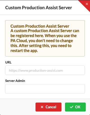
In the Custom Production Assist Server dialog, an invalid URL format displays an error at the URL field and leaves the dialog open. If the URL is valid but the server is unreachable, OK closes the dialog and Production Assist displays an error message. If the check succeeds, Production Assist saves the new connection and displays a confirmation. The screenshot uses the URL placeholder and an empty Server Administrator field as an example. Cancel closes the dialog without applying the entry. Use the dialog only if you actually use your own Production Assist server.
Open Help → About Production Assist to check the installed build. The dialog shows Build Type, Version Number, GitHash, and Build Number separately for Core and UI. In a plugin environment it also shows Plugin DLL Path and Web Interface Path; use Open Parent Folder to open an available local path. If there is no local path, the folder button is disabled. OK or the red close icon closes the dialog. The long view is scrollable. The audit screenshot uses sample values and shows only part of the lower path area.
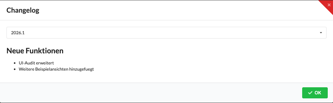
Open Help → What’s new to view the release notes. By default, the dialog selects the latest version that has release notes; if no version has notes, it selects the first available entry. Choose another version from the dropdown to display its notes. The dialog loads the version list and content from the internet; a loading indicator appears while it loads. If the request fails or a version has no release notes, the dialog does not display its own error message. Close it with OK or the red close icon. The shown UI audit screenshot reflects the current component layout and version selector, but uses the generic fixture title Changelog instead of the current menu title What’s new.
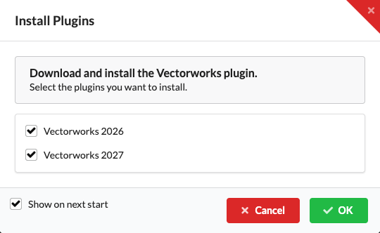
The dialog lists the plugin targets Production Assist detected for the selected host application. Select the installed host applications for which you want to install or update a plugin. Host applications that are not installed are disabled; an already installed plugin is marked Currently Installed. If a detected host application is already running, its entry remains disabled until you close the application and check the status in the dialog again. OK downloads the selected packages and starts their setup. If nothing is selected, no package is installed. Cancel or the close icon also exits the dialog without installing anything. The Show on next launch option controls whether Production Assist displays this installation notice again the next time it starts; the setting is saved both with OK and when you cancel. If no matching targets are detected, the list remains empty. The UI audit screenshot shows a synthetic installed Vectorworks 2026 target without a plugin already installed; it does not indicate the installation state on a real device.
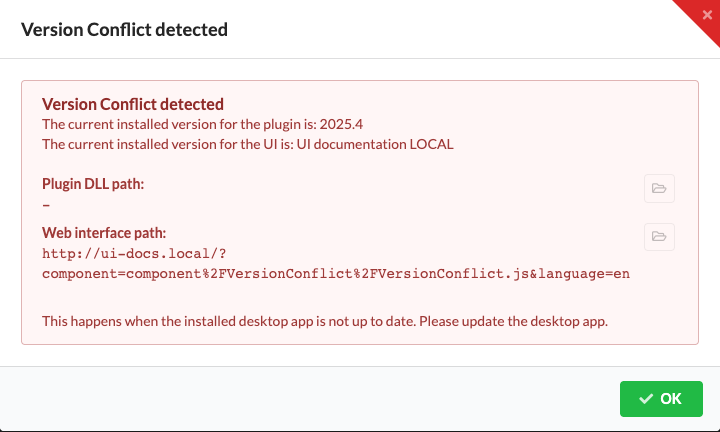
At startup, the desktop app checks installed plugins in its data folder against their saved version. If a matching version for the current app version is missing, it offers an update. Loading the updated module in AutoCAD or BricsCAD still depends on the respective APPLOAD setup.
If the desktop app version or build does not match the installed plugin, Production Assist displays the Version Conflict Detected dialog at startup. Check the displayed versions and paths. The rendered view uses sample values. A folder button opens the displayed local path; if there is no local path, it is disabled. OK closes the notice. Then update the desktop app or install the matching plugin.
The macOS desktop app also has the system-standard Production Assist app menu. The UI renderer shows only the integrated About Production Assist command here. macOS provides entries such as Services, Hide, and Quit; they are not part of the rendered product interface.
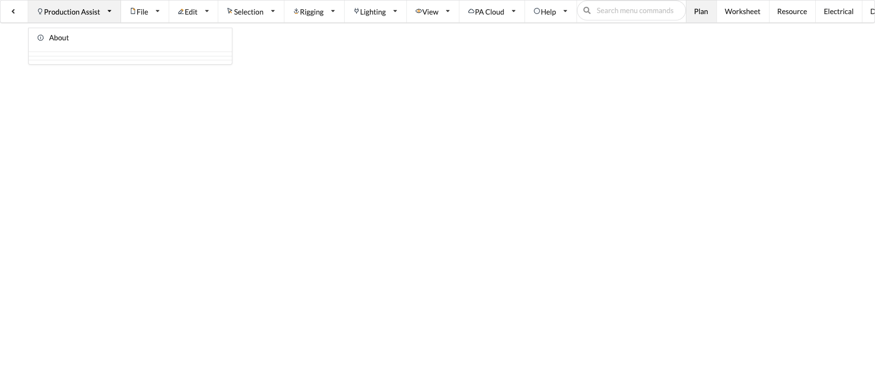
| Command | What happens | Requirement |
|---|---|---|
| About Production Assist | Opens the same dialog with version and build information, plugin paths (if available), and folder buttons. | macOS desktop app. |
| Services | Displays system-wide macOS services. | macOS desktop app. |
| Hide | Hides Production Assist. | macOS desktop app. |
| Hide Others | Hides all other applications. | macOS desktop app. |
| Show | Unhides the app. | macOS desktop app. |
| Quit | Completely quits Production Assist. | macOS desktop app. |
| Speech | Opens system commands for spoken output. | macOS desktop app. |
| Start Speaking | Starts macOS speech output. | macOS desktop app with speech output available. |
| Stop Speaking | Stops macOS speech output. | Speech output is running. |
The Development menu appears only in development builds. Its items are intended for diagnostics and development and are not included in regular builds.
Opens the submenu with the Run All Core Unit Tests command and the currently registered individual tests. The list of individual tests depends on the build.
| Command | What happens | Requirement |
|---|---|---|
| Run All Core Unit Tests | Starts the registered Core unit test suite. | Development build. |
| Individual Core Unit Tests | Starts the selected individual test. Available names change with the tests registered in the build. | Development build with registered test names. |
| Command | What happens | Requirement |
|---|---|---|
| Run WASM Stress Test | Starts the WASM stress test. | Development build. |
| Open Logg-Viewer... | Opens the desktop app's Logg Viewer. | Development build in the Electron desktop app. |