

Production Assist follows a scheme that can be summarized as a hierarchical object-geometry model.
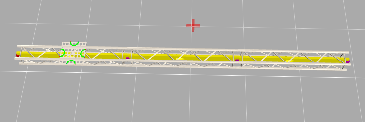
When a new project is created, it initially contains no objects. When a new object is added, that object can be subordinated to any other objects as desired. This is illustrated below with an Assembly Group T1 and a Eurotruss truss.
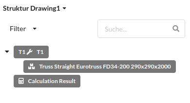
Each object can be subordinated to any other object, making complex tree structures possible. The tree structure makes it possible to group a series of objects together and to move, rotate, and scale them as one unit.
It does not matter what an object actually represents, whether it is a group, a truss, a fixture, or a chair.
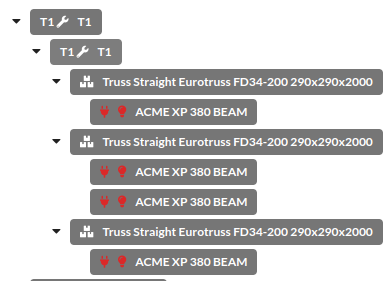
An object can also take on any number of functions and, for example, combine elements of a chain hoist and a truss.
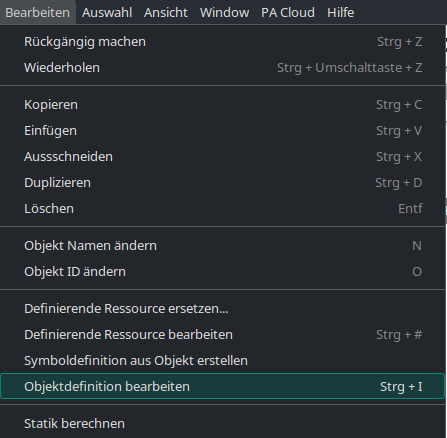
What functions an object actually has and what it looks like is defined by its geometries. To view the geometries of an object, the object must be selected and then the menu item
Edit -> Edit Object Definition
must be clicked.
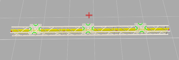
In many cases, only one geometry source can be recognized there: the symbol definition.
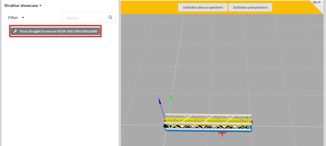
The symbol definition (also called the defining resource) allows geometries to be shared between multiple objects.
A typical example of symbol definitions is trusses: each truss type has its own symbol definition. If the symbol definition of an Eurotruss FD34-200 is edited, all trusses of this type in the drawing will change.
This makes it possible to control the geometries of all objects very precisely:
Geometries do not only determine the appearance of an object, but also the related entries in the Object Properties. Depending on the geometry, properties for connectors, suspension points, or other functional areas of an object are created there.
All objects receive their properties through the geometries they contain. If an object contains multiple geometries with different functions, it also brings along the matching properties for those functions.
Array Properties are repeatable property groups such as multiple connectors or multiple suspension points that are generated dynamically from the geometries they contain. Each geometry that brings such a property group contributes its own entry.
This means a single object can have more than one property of the same type, for example multiple connectors or multiple suspension points.
In the Object Properties, these values appear as multiple entries of the same property type within the relevant object area. They can be viewed and edited there.
Which Array Properties are visible always depends on which geometries the object contains.
The object definition and the symbol definition follow the concept of a tree structure. Geometries can be grouped within them or subordinated hierarchically.
As in the normal editor, a range of tools is available in the object/symbol definition editor. More detailed instructions for the individual tools can be found in the symbol construction guide.