

Right-click an object in the Scene Tree or Renderer to open its context menu. The available commands depend on the object and the selection. Right-clicking an empty area in the Renderer offers only Add → Assembly Group. Text fields and preset entries have their own context menus.
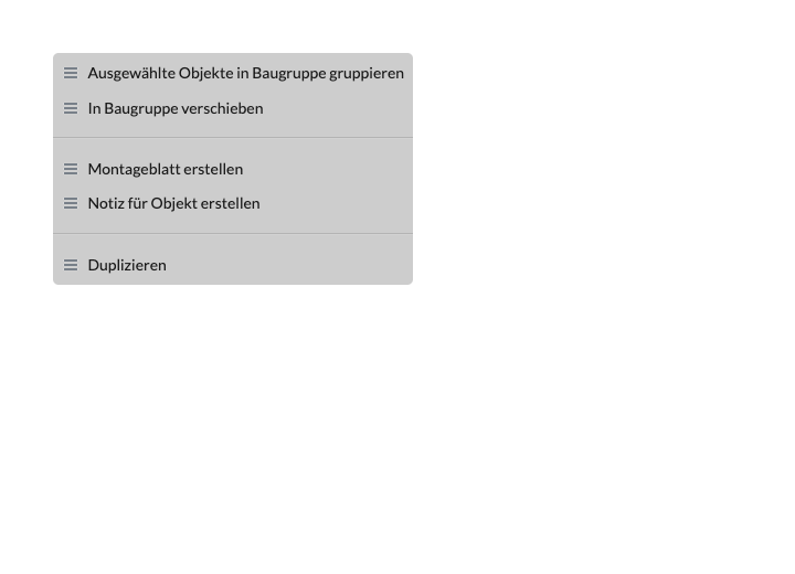
Use Add → Assembly Group to create an empty assembly group. Open the command on the intended parent object to add the new group beneath it. In an empty area of the Renderer, the group is created at the clicked point. To combine objects that are already selected into an assembly group, use Group Selected Objects into Assembly Group.
Rename Object or Change Object ID places the input focus in the corresponding field in Object Properties. First select the object you want to edit, change the value in the Name or Object ID field, and confirm the entry there. These commands do not automatically assign a new name or ID.
Select All selects the objects in the current drawing that can generally be displayed in the Scene Tree. Objects excluded from the Scene Tree are not additionally selected. The menu bar has the same command under Selection → Select All.
This command combines at least two selected objects into a new assembly group (Assembly Group). A single object does not trigger grouping.
There is currently no suitable up-to-date image for Create Assembly Group. The existing UI-audit render incorrectly shows the title About Production Assist and the English field Group Name. Therefore, do not use it as an image of this dialog. The fields and name validation have been checked against the dialog implementation.
| Field | Effect |
|---|---|
| Assembly Group Name | Name of the new Assembly Group. Group is prefilled when the dialog opens; replace it with a descriptive name. Empty names and names that match an existing assembly group after leading and trailing spaces are removed (case-insensitively) are not allowed. For a duplicate name, the message An assembly group with this name already exists. appears. |
| OK | Active only when the name is non-empty and unused. Creates an assembly group containing the selected objects. Leading and trailing spaces are removed before creation. |
| Cancel | Closes the naming prompt without grouping the objects. |
The dialog prevents empty and already-used names; OK remains disabled in both cases. Change the name until the error message disappears. Choose Cancel, press Escape, or click outside the dialog to close it without grouping. After successful creation, find the assembly group in the Scene Tree. At least two objects must be selected before you open the command.
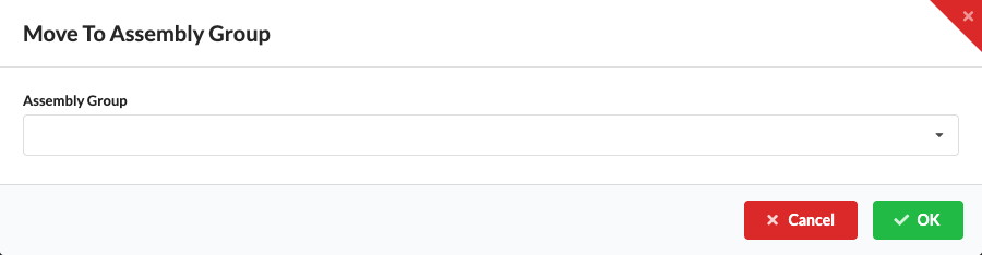
Use Move into Assembly Group to assign selected objects to an existing assembly group. The dialog lists all assembly groups in the current drawing.
If no suitable assembly group is available, create one first. Select a destination in the Assembly Group field before selecting OK. The field is empty when the dialog opens, and OK is enabled. Without a destination, the assignment is not made; the current dialog call opens the selection again. Select Cancel to close the dialog without making a change.
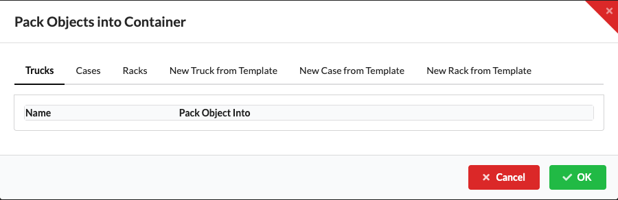
Use Pack into Container... to assign selected objects to an existing container, case, or rack for transport planning. In the Pack Objects into Container dialog, you can instead create a new container or case from a template. Create templates in the Resource Manager.
The rendered dialog shows the current tabs and actions with an empty example list.
You can also link cases and racks to a truck for transport; the container and case guide describes the assignment.
Select an assembly group and choose Dissolve Assembly Group. The assembly group is deleted; its child objects remain in the drawing. Check the resulting hierarchy in the Scene Tree.
This command automatically connects compatible power ports within an assembly group. The assembly group must contain both consumers (Consumer) and distributors (Distributor) with compatible, free ports.
The command processes the child objects of the selected assembly group. The Patch Tool Order setting determines whether patching follows their stored hierarchy order in the Scene Tree or their positions on the structure. The visible sort order of the Scene Tree does not change the patch order. This does not guarantee that assignments follow the nearest objects in space.
This command connects compatible data ports on the child objects of an assembly group. Select the assembly group and choose Patch → Data Patch Child Objects. Then check the data connections in Object Properties. Only compatible, free inputs are considered; a complete daisy chain for all fixtures is not guaranteed.
By default, DMX addresses use the current fixture mode. In File → Settings... → Electrical (settings), you can instead select Biggest Mode in the DMX Patching Mode field.
Select consumers and distributors with compatible power ports. Right-click a selected object with a power port to show Patch → Power Patch Selected Objects. The command processes the current selection in 1:1 mode: each free output is assigned to a free input. Already connected inputs are skipped. To fill up to the configured power reserve, use Lighting → Power Patch Fill Current in the menu bar.
Select fixtures with compatible data ports and right-click one of the selected fixtures. Choose Patch → Data Patch Selected Objects. The command processes the current selection and connects compatible, free inputs to outputs. Check the resulting connections in Object Properties; not every selected fixture must become part of a continuous daisy chain.
The order is determined by Patch Tool Order in Electrical Settings. DMX Patching Mode is set to Current Mode by default; Biggest Mode is also available.
This command appears under Patch when you open the context menu on an object with a power port. However, the current menu call does not pass the information the resolve command needs, so this route does not change any connections. Check outputs with multiple assignments in Object Properties and correct the assignments there.
Select an object in the Scene Tree or Renderer and right-click to open its context menu. Choose Change Defining Resource to open the resource selector and assign a different resource to the object. The command is active only for eligible objects, such as meshes and objects with a defining resource. Choose a resource from the current drawing, local resources, or online resources, and import it if needed. An internet connection is required for online resources that are not yet available locally.
Use Sort... in an assembly group's context menu to change the order of its child objects. Depending on your goal, choose Sort Child Fixtures by ID, Sort Child Fixtures by Name, Sort Child Fixtures by Position on Structure, Sort Child Objects by Object ID, or Sort by Resource Type. Position-based sorting applies to objects on detected structural lines.
These commands reorder the objects in the drawing. Sorting the display in the Scene Tree is a separate function that sorts the tree view by a selected field.
Use Create Assembly Sheet to create a sheet for the clicked object or current object selection. Assembly sheets organize setup tasks and can be used in Paperwork.
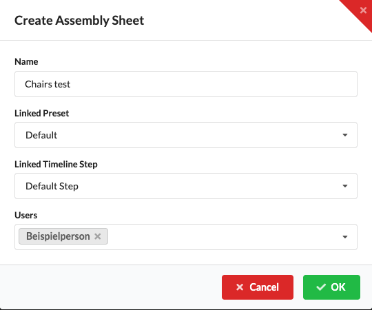
For other ways to create sheets and use them for tasks, see the assembly sheet guide.
Select an object and choose Create Object Note from its context menu. The full-screen dialog contains a Markdown editor with Write and Preview tabs. Write the note under Write and check the formatted view under Preview. The editor toolbar provides formatting commands; Saved View and Assembly Sheet insert references to the corresponding content.
Select OK to save the note on the selected object. Clicking outside the dialog does not close it. If you select Cancel after making a change, Save Data and Discard Data appear. Currently, both buttons close the dialog, but Save Data does not create the note. Use OK to save it. The red close icon and Escape also close the dialog without creating the note. In the task overview, you can reopen saved notes on the objects of an assembly sheet. Whether other people can see them depends on whether the drawing has been transferred to a shared online project and whether they have access to it.
There is currently no suitable image for this dialog: the existing UI-audit capture shows the editor toolbar as an incomplete list rather than a usable toolbar. It is therefore not used as an image of the dialog. Use Write to edit and Preview to see the preview.
Delete removes the clicked object. If it is already part of a multi-selection, the command removes the selected objects instead. Check the selection in the Scene Tree or Renderer before deleting. You can undo the change with Edit → Undo.
Copy and Cut operate on the current selection; Cut removes the selected objects from the drawing. Use Paste to insert the contents of the Production Assist clipboard. Select the objects before opening the context menu. Duplicate creates a copy of the clicked object. To make multiple copies in a pattern, use Duplicate and Arrange Selected Objects.
Use Duplicate and Arrange Selected Objects to create copies of the selection in a line, rectangular grid, or circle.
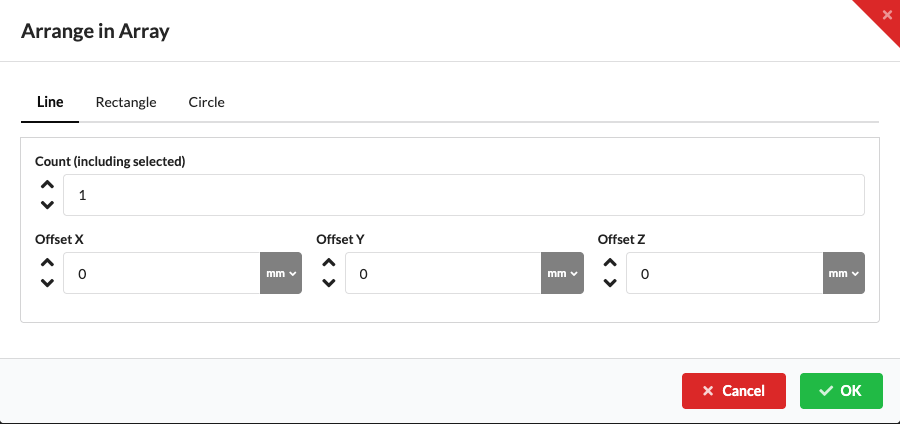
Alternatively, use Selection → Apply to Selection → Arrange Selected Objects to rearrange an existing selection without creating copies. The fields for all three patterns are described there.
Open the context menu on an object with structural geometry and choose Select Objects on Child Structure. Production Assist selects the objects in the detected connected structure. If the structure check finds no connected section, no additional objects are selected. The command does not clear an existing selection.
Use Place Objects on Child Structures to place new fixtures, symbols, or meshes along the structural geometry of an Assembly Group. For a directly selected structure, Place Objects on Selected Structures... is also available in the context menu and under Selection → Apply to Selection.
To distribute already selected objects, select those objects before opening the dialog and switch to Existing Selected Objects. The dialog moves them onto the enabled structure instead of creating new resources. If multiple structures are enabled, only the first one is used; the dialog displays a warning. The Count is fixed to the number of selected objects on this tab.
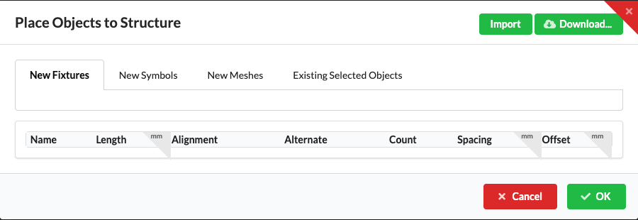
The audit capture uses empty example data. In your drawing, the resource and structure rows depend on the available content and your selection.
Placing objects alone does not ensure a structurally effective connection. Then check supports and other rigging objects in the structural model.
For an influence line, Select Overloaded Objects may be available. This command replaces the current selection with the objects identified as overloaded for that influence line. If no overloaded objects are associated with it, the selection remains empty. Select Influence Line Target Object appears when you right-click a marked target object in the Renderer and selects that target.
When you click structural geometry in the Renderer, Show Results for Selected Structure appears. Use the command after a structural calculation to view results for that structure. Without calculated results, there is no analysis for the clicked structure.
Switch to Beam View opens Beam View focused on the clicked object or geometry. There you can inspect the available beams in 2D. The command does not start a calculation.
Select an assembly group with child objects and choose Select Child Objects. The command adds its direct child objects to the current selection. For objects nested more deeply, open the command on the relevant child assembly group.
Select an assembly group with child objects and choose Collapse Child Objects. The assembly group and its subgroups are collapsed in the Scene Tree. The objects remain in the drawing; the command does not change their visibility in the Renderer.
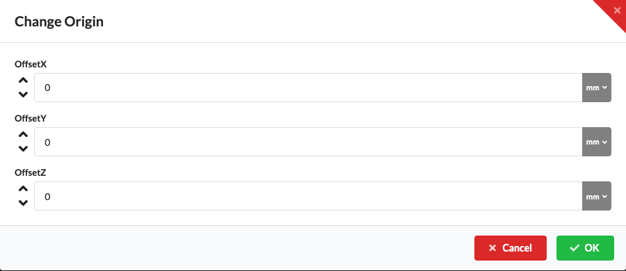
When grouping objects, Production Assist sets the new assembly group's origin based on the center of the selected object positions. To change it later, open Change Assembly Group Origin on the assembly group or one of its child objects. The Change Origin dialog loads the current offset of the associated assembly group into the OffsetX, OffsetY, and OffsetZ fields. Adjust the coordinates in the displayed length unit and select OK. Production Assist changes the assembly group's origin in the global coordinate system; then check the origin and object positions in the Renderer. Cancel closes the dialog without applying the change.
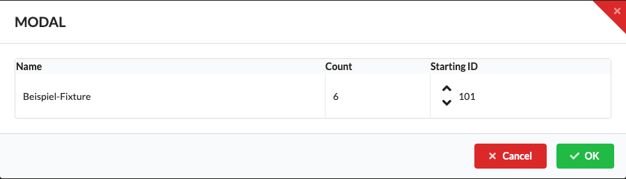
This command assigns sequential fixture IDs by fixture type. Open it from the context menu of the parent object whose child fixtures you want to number. The command also appears on other objects; if they have no fixtures beneath them, the table remains empty.
The current capture shows one fixture type with example values. The dialog has no title in the application; Automatically Number Fixture IDs is the context menu command. The UI-audit renderer uses the technical placeholder MODAL as its title.
Select the affected object and choose Report Symbol Error Online.... Production Assist opens the Online Feedback dialog and loads an externally hosted feedback form in it. Select OK to close the dialog. The form is loaded from an online service and requires an internet connection. The locally rendered view shows only the dialog frame; the contents, required fields, and submission of the external form cannot be checked there. The command does not change the symbol in the drawing. Help → Report Symbol... also opens this dialog to report a symbol; Help → Feedback... uses it for general feedback.
