

This page explains the workflow and settings for the integrated static calculation in Production Assist. Production Assist reads the drawing and automatically derives the static model, including structural elements, connections, loads, and supports. You do not need to build the calculation model separately from nodes, members, and loads: the geometry and properties of the drawn objects are decisive. When real-time calculation is active, the model is recalculated automatically after changes relevant to the calculation; otherwise, start the calculation when needed. The results also depend on cross-sections, load groups, and load combinations. For the basics of static systems, see Statics Know-How; specific steps for inserting individual objects are on the linked detail pages.
Production Assist automatically reads the drawing objects relevant to the static calculation and derives structural elements, connections, loads, and supports from them. The standard calculation also includes objects on hidden layers and classes. You do not need to build the calculation model separately from nodes, members, and loads: the drawing and the properties of its objects provide the inputs.
| Production Assist derives automatically | You define or check |
|---|---|
| Structure: Structural geometry in truss symbol definitions or directly on objects becomes calculable structural elements. | Compare the structural geometry highlighted in yellow with the drawn construction. Check the cross-sections, and choose between global and internal structure only if the symbol geometry is prepared for it. |
| Loads: Object weight and load behavior determine whether a force is included as a point, line, area, or spatially distributed 3D load. | Check that Use as Load, load behavior, load application point, and load group match the actual construction. |
| Connections and supports: Production Assist evaluates the geometry and properties of the drawing objects. | Check that the recognized connections and supports represent the actual force path and can transfer the intended forces. |
| Calculation cases: The active combination for structure, supports, and tipping/sliding controls the corresponding calculation purpose. | Check the three colored selections and their factors. A complete calculation evaluates all three purposes; the combinations can differ from one another. |
The automatic process can only account for what is present in the drawing and object properties. If geometry, loads, or supports are missing or configured incorrectly, the derived calculation model will not represent the setup as intended.
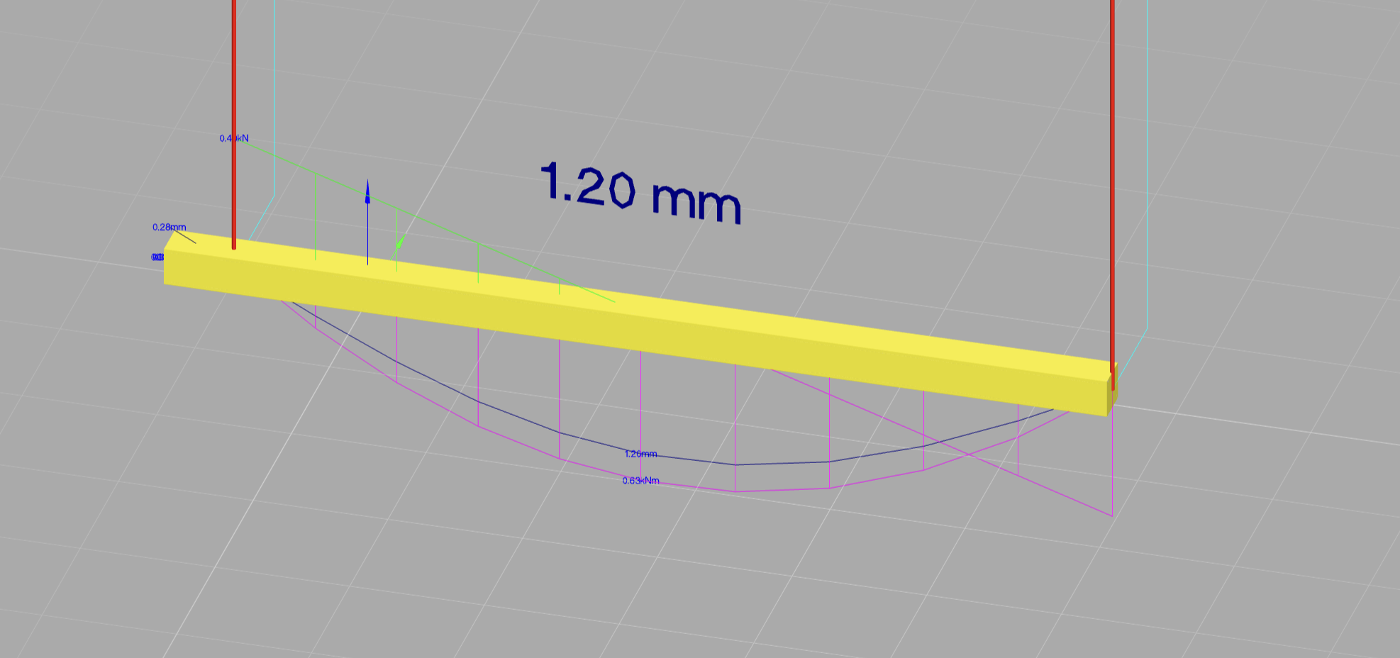
The yellow view shows the idealized structural geometry that Production Assist calculates for a truss. The example represents the truss as a simplified structural member. Result plots below the truss show shear force, bending moment, and deflection; the displayed numerical values belong to these results. The display unit for deflections is determined by Unit for Dimensions in Print in App Settings. For example, lengths can be shown in meters and deflections in millimeters. Enable Show Structure in Renderer Settings to check which load-bearing lines were recognized.
The next view shows the same truss with its component geometry and result plots, but without the yellow highlighting of the idealized structure. Toggle Show Structure on and off to compare the calculated structural model with the drawn truss and identify missing or unexpected structural elements.
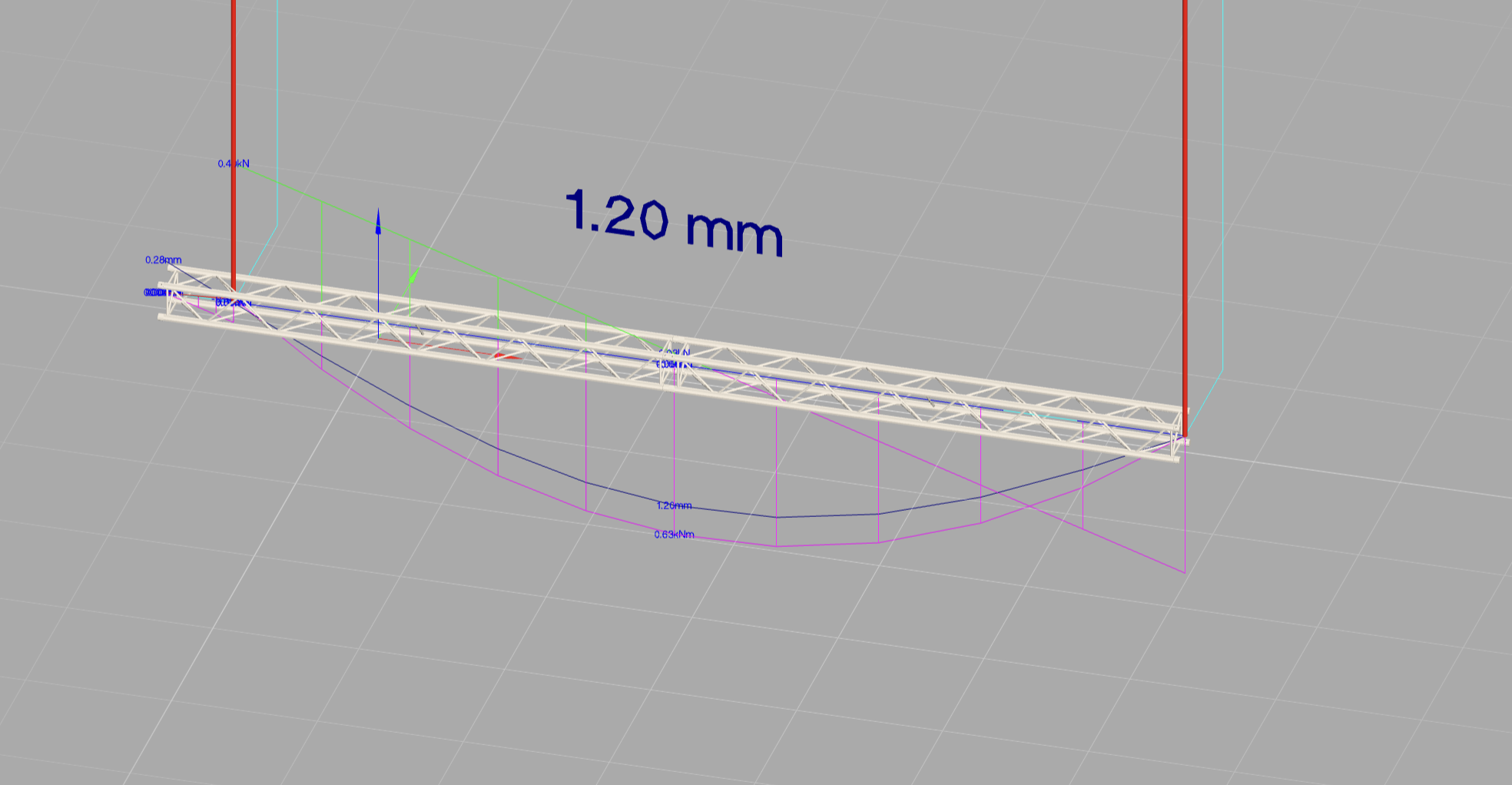
Under Internal Forces in the navigation, you can show or hide individual result types, such as shear force, bending moment, or deformation. Internal forces are forces and moments within the structure; deformation is displayed as a separate result plot. These switches change only the display, not the calculation. Details are in Internal Forces in the Navigation.
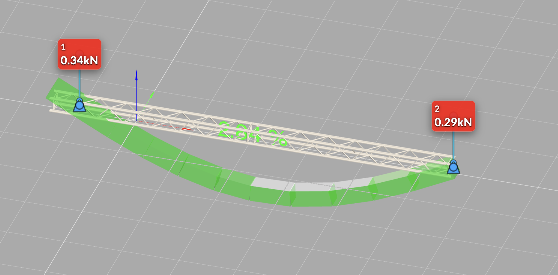
The third view adds support reactions and a deformed utilization display to the structure and result plots. The internal forces use the green load combination; the support forces follow the blue selection. After each calculation, check whether the deformation shape and reactions match the expected force path and whether utilization is below the relevant limits. The assignment and defaults are explained under Load Combinations and Result Values.
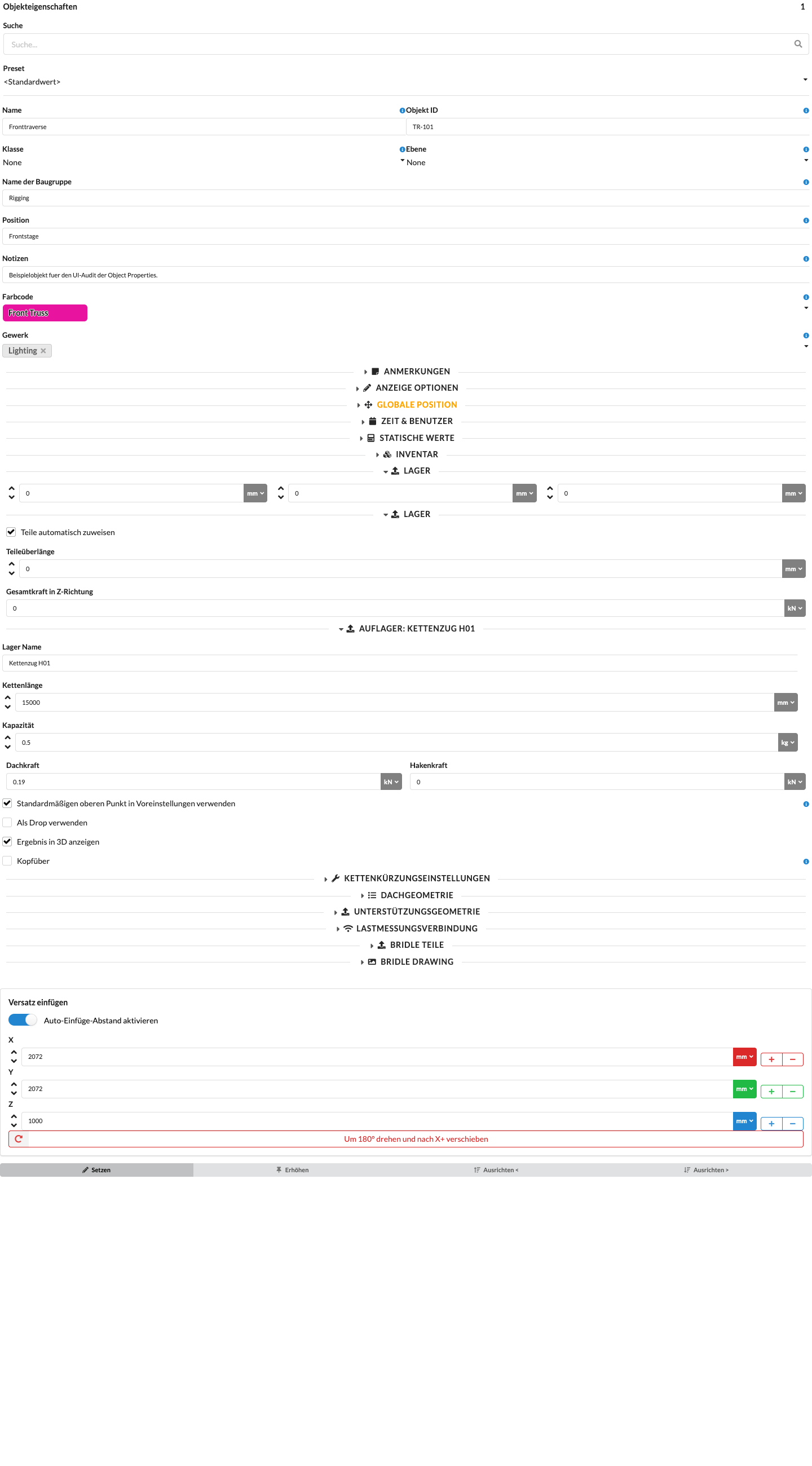
For a hoist, first enable the display of support forces for the relevant support in Object Properties: open Support → Support: Hoist, select the support, and enable Show Result in 3D. This setting enables the result label for that support, but does not start a calculation or change the results.
The global display of 3D labels must also be enabled. Turn on Show Labels in 3D in Renderer Settings or in the 3D renderer's Quick Settings. Hover over the relevant icon or focus it with the keyboard to read its description, then click it. Both settings must be enabled for the permitted hoist values to appear in the model.
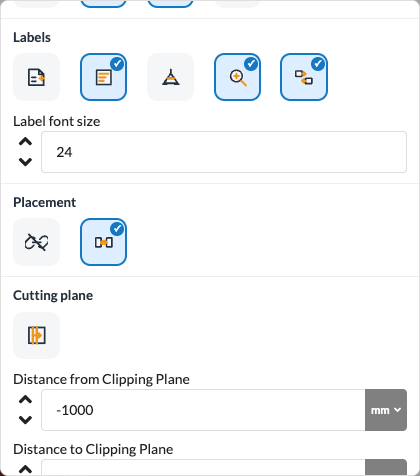
Automatically generated ground supports use a separate renderer option: Show labels for automatically generated supports. You can find the icon in Quick Settings or under Renderer Settings. Hover over it or focus it with the keyboard to read its description. After a successful calculation, this option displays the X, Y, and Z reactions and is independent of Show Result in 3D on the hoist. The two types of labels and their settings are described in Renderer Settings.
Production Assist creates the calculation model from the drawing. This sequence helps you check the automatic derivation and its inputs before reviewing the results.
The integrated calculation is a tool for examining the model derived from the drawing and its results. On its own, it does not provide professional approval for construction. An exported calculation report documents selected inputs and results, but it also does not replace a reviewed structural calculation; details are in Create a Calculation Report. Use results only if you can understand and professionally assess the model, load assumptions, supports, and checks. If it is unclear what Production Assist calculates or why a result is plausible, have a qualified professional review the model before using it.
Production Assist has an in-house engineering office that can support you with structural calculations for temporary structures, from truss structures to special constructions. Learn more about the service at Static Office. You can request a reviewed calculation for the current state of an online project using File → Request Reviewed Static Calculation...; Request a Reviewed Static Calculation describes the requirements and process.
The calculation scope determines which objects Production Assist includes in the calculation. By default, this is the entire drawing. Production Assist reads all existing drawing objects that are relevant to statics, including objects on hidden layers or classes. A layer or class explicitly marked Exclude from Calculation is left out.
Because the default scope includes the whole drawing, pay particular attention to structures drawn twice or on top of one another. Overlapping trusses or members can be recognized as additional load-bearing elements and distort stiffness, dead weight, load distribution, and reactions. When checking the model, show layers and classes one at a time, use the visibility controls, and compare the calculated structure with the drawn geometry. Hiding objects alone does not remove them from the default calculation; enable Calculate Visible Objects Only or set a suitable calculation scope for that.
Narrow the scope only when you deliberately want to examine a partial model. There are three distinct settings:

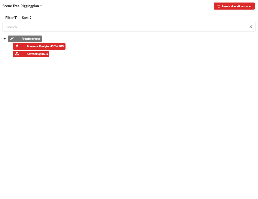
The two footer filters can be combined. Calculate Selected Objects Only follows the current selection; the fixed calculation scope is a separate, saved limit. If a result is unexpectedly small or incomplete, check both footer icons and the fixed scope. To calculate the whole drawing, turn both filters off and choose Rigging → Calculation Scope → Reset Objects to Calculate, click the Reset calculation scope button in the Scene Tree, or choose Reset Calculation in Selection Groups. This does not delete saved calculation results.
In the layer and class lists, Only Visible isolates a layer or class by temporarily hiding the others. This visibility limits the calculation only if Calculate Visible Objects Only is also enabled in the footer. The icons and their effects are described in Classes in Navigation and Layers in Navigation. To return to the normal view, turn Only Visible off for the isolated layer or class. To stop using the current visibility as a calculation filter, also turn off Calculate Visible Objects Only in the footer.
The calculator icon in the Information Line at the bottom toggles real-time calculation. You can also find the same option under File → Settings → App → Static Calculation Settings → Use Live Static Calculation. Green means Production Assist automatically recalculates in the background after model changes that affect the calculation; gray means changes do not trigger automatic recalculation. Real-time calculation is enabled by default. Turning it on does not itself start a calculation run. To calculate immediately, choose Rigging → Calculate Statics; this command also works when live calculation is off.
For large models, turning real-time calculation off can make editing smoother. Then calculate deliberately after relevant model changes. Disable Partial Calculation and Abort Calculation on Errors under File → Settings → App → Static Calculation Settings also affects how model errors are handled: when enabled, calculation stops at an error; when disabled, Production Assist attempts a partial calculation of valid model areas.
If Show Calculation Summary After Calculation is enabled under File → Settings → App → Static Calculation Settings, the Calculation Summary opens automatically after a calculation run. There you can check the status, errors, loads, and verifications. You can also open the summary at any time using Rigging → Show Calculation Summary.... The results summary and its sections are described in Calculation Summary.

Production Assist automatically creates the static model from the drawing. It reads the objects and their structural geometry and derives the structural elements that can be calculated. Trusses contain this geometry in their symbol definition or directly on the object. You therefore do not need to draw the structural elements again as a separate calculation model. A derived structural element has, among other things, start and end nodes, a direction, and a cross-section. The geometry determines where loads and supports act and how members are connected.
A cross-section provides the profile and material values required for the calculation, such as area, moments of inertia, resistance, and dead weight. You can assign a different cross-section to an object in Object Properties → Static Properties → Override Cross Section. For members with multiple cross-sections, check the assignments in the symbol definition. See Structure Elements in the Symbol Workflow and Static Properties.
The dead weight of a structural element is calculated from its cross-section and material. If the object's dead weight is zero, Production Assist generally uses the line load stored in the cross-section as a substitute. No dead weight is applied to Ground Supports in ballast calculation mode; the substitute is not used in that case. Check both the object weight and cross-section data, as well as the configured load group.
By default, Production Assist represents the structure as a global structure: a structural element is calculated as a simplified equivalent member along its structural centerline. For example, this allows a truss to be modeled as a single member with the stored cross-section values.
The Calculate Internal Members setting in the Settings profile switches to calculating the prepared internal structure. The chords and braces marked as internal structure are then used instead of only the simplified centerline member. This is useful when individual tubes and braces, one-sided bracing, or a special connection position are decisive. For this, the symbol definition must contain internal geometry on the assigned Structural Lines layers. Without this prepared data, the switch does not provide additional structural detail.
The global structure and internal structure are different calculation models. Switch between them only when the symbol geometry is prepared for the selected mode, and check connections, cross-sections, and results again after switching.
When File → Settings → App → Generate Truss Crosses Automatically is enabled, the static calculation detects suitable intersections of structural elements and creates Truss Crosses there. The option is enabled by default. Detection takes into account, among other things, position, direction, cross-section permissions, and whether the elements belong to the same object. Allow Truss Crosses in the Same Object also controls whether such intersections within one object are included. A cross-section can also prevent automatic creation between elements.
Truss Crosses connect intersecting structural elements; their connection properties determine which forces or moments the connection can transfer. Disable automatic creation if you want to create the connections manually. For partial calculations, associated Truss Crosses are not added automatically by default. Automatically Add Truss Crosses for Partial Calculation adds them when the connected structural objects are included in the calculation. See Create and Check Truss Crosses for details.
Drops connect structural elements to one another through a suspension or support. The command Rigging → Connections → Create Drops searches selected structural objects for intersections between different objects. A Drop can be created there when the height difference is more than 100 mm; existing Drops at the same points are skipped. The calculation can also treat a connection as a Drop when Use as Drop is enabled for the relevant support geometry. For new Bridles, File → Settings → App → Use as Drop for New Bridle can preselect this property. This setting affects the calculation model; it does not replace checking that the connection exists and is correctly attached in the actual construction.
Manually created and automatically generated Drops must be at the intended points. Check their connections and the resulting forces in the results. Insertion and editing steps are described in Insert Drops at Structural Intersections and Ground Support Attachments.
Production Assist reads the entire drawing and automatically derives loads from the drawing objects. When Use as Load is enabled, the object's weight and load definition are included in the structural model. The object geometry and configured load behavior determine whether the force is transferred at a single point, along a length, over an area, or spatially through a 3D body. You do not need to build the calculation model separately: draw the structure, then check that the detected loads, application points, and assignments match the real setup.
| Load Type | Effect in the Model | Typical Use |
|---|---|---|
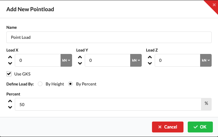
| Point Load | A force acts at a single position. The Insert Point Load dialog uses force components in kN and can specify the position by height or percentage. | An individual device, weight, or defined force at a connection. |
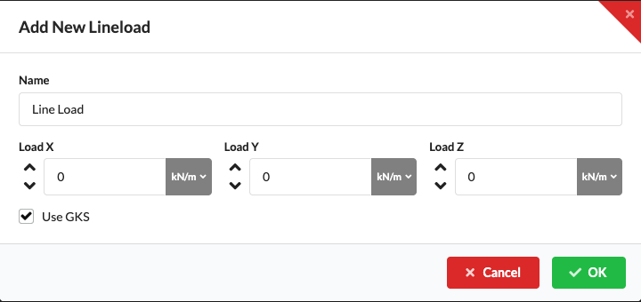
| Line Load | A load is distributed along a line or structural length. In the Add Line Load dialog, components are specified in kN/m; the resulting force increases with the loaded length. | Cable bundles, an LED bar, or another load distributed evenly along a member. |
| Area Load | The weight of a planar object or an additional standard-based area load value is applied over a polygon area and transferred to adjacent structural members. | A floor, covering, banner, or another planar load area. |
| 3D Load | The 3D geometry of a solid is used to distribute its weight spatially to adjacent structural members. | Decoration or another object whose actual body determines the load distribution. |
Wind loads are a separate load type: their direction and magnitude also depend on the wind model, location, and wind load area. Load groups and load combinations control the calculation cases in which these and other loads are included, and the factors applied to them. Check the weight, direction, and group assignment in Object Properties. For a detailed explanation of area, 3D, and suspended loads, see Load Behavior.
A point load acts at a single position. For a load object, its application point is at the object's insertion point unless an offset is set. In the 3D Renderer, you can move the application point using the small Weight icon: enable Select or Move, select the load object, click the Weight icon at its current point, and then click the desired position on the supporting structure. Production Assist saves this Load Offset; the object itself does not move.
To assign the load to the supporting structure, Production Assist uses the load point calculated as 3D object position + transformed Load Offset. The center of gravity does not move this matching point. If the load object has geometries with positive partial weights, their center of gravity offset is then added to the load point. For the eccentricity moment, the offset from the truss connection point to the load point and the center of gravity offset are taken into account together.
The Insert Point Load dialog records force components in kN and lets you define the application point by height or percentage. This is different from an object's weight, which is included as a load through its Object Properties.
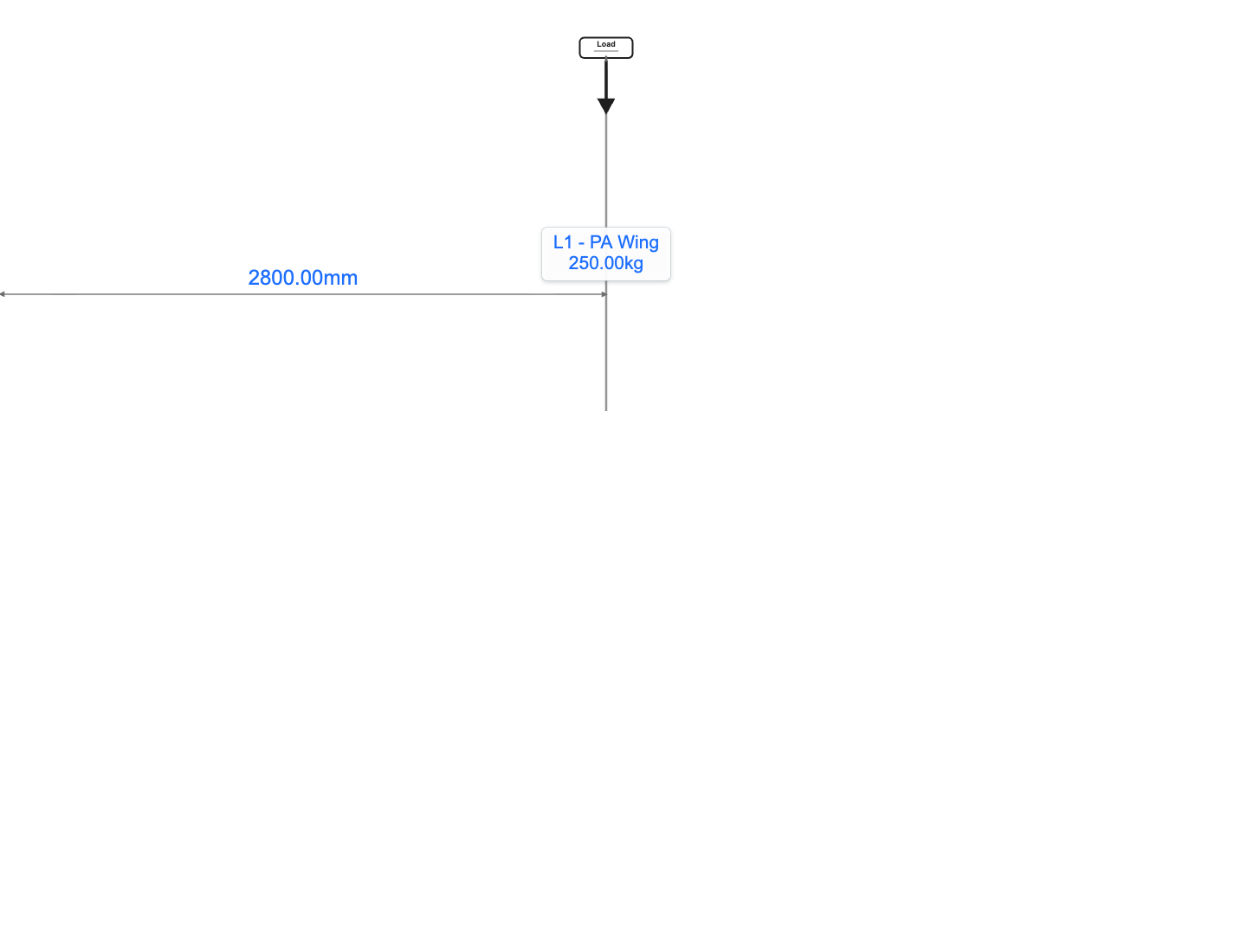
In Beam Mode, the Renderer shows the position of an individual load and its distance from the start of the beam. This view helps you check the detected application point on the calculated structure. You can also show or hide the load labels for point and line loads in the Renderer settings.
For each geometry, you can set a weight and local center of gravity coordinates in Edit Mode. Object Properties describes these fields. Production Assist transforms the points into the drawing and calculates the geometry's center of gravity as the sum of partial weight × center of gravity position, divided by the sum of the positive partial weights. The transformed Load Offset is added once. For example, for unrotated and unscaled geometry at the object origin, 10 kg at X = 0 and 30 kg at X = 1 m result in a center of gravity offset of X = 0.75 m. With a Load Offset of X = 0.20 m, the load center of gravity is at X = 0.95 m relative to the object origin; the load application point remains at X = 0.20 m. The total weight of the load object remains the Weight value on the drawing object.
For an ordinary object point load, matching and eccentricity are separate: Load point = 3D object position + transformed Load Offset. This point determines the assigned truss and the connection position on its axis. Lever arm = (load point − truss connection point) + transformed center of gravity offset. The additional moment is lever arm × load force. The offsets are added as directed vectors and can therefore reinforce or partly cancel each other. Example perpendicular to the truss: if the load point is 100 mm beside the truss axis and the center of gravity is another 50 mm in the same direction, the lever arm is 150 mm. With a center of gravity offset of 50 mm toward the axis, 50 mm remains. The center of gravity itself is not used for matching.
The distance from the resulting load center of gravity to the connection point also contributes an eccentricity moment to the static calculation for load portions transferred along a line, over an area, or through a 3D body. Their connection points remain in place. The self-weight of load-bearing structural elements continues to be distributed through the structural model; if a geometry center of gravity is defined for the object, its offset is also taken into account.
Show Center of Gravity under Navigation → Section Reactions displays the weighted center of the downward loads for each connected static system. Point loads, nodal loads, and line loads, including structural self-weights, are taken into account. The factors of the active support load combination apply; disabled load portions do not contribute. Wind forces and additional horizontal equivalent loads are not included as mass. The center of gravity is calculated from the load points, not derived from the support reactions. This also preserves the actual height of a defined load center of gravity. No center of gravity marker appears when there are no effective weight loads.
In the 3D Renderer, a quartered black-and-white circle with a black ring and thin magenta border marks the exact center of gravity, including the Load Offset. Each pair of diagonally opposite quarters has the same color. The center of the symbol lies at the calculated point. The symbol faces the view and remains visible in front of occluding geometry and while selecting results. Recalculate the results after changing Load Offset, geometry weights, or center of gravity coordinates.
The center of gravity symbol and tilt display are also available directly in Vectorworks, SketchUp, and AutoCAD/BricsCAD. Enable Show Center of Gravity. In Vectorworks, the ProductionAssist-Geometries-Influence Line-Center of Gravity class must also be visible. In SketchUp, enable Production Assist - Results under Window > Overlays; the display remains visible in front of occluding geometry. In AutoCAD/BricsCAD, thaw the result layers ProductionAssist__CenterOfGravity and, for the angle label, ProductionAssist__CenterOfGravity_Text; these names apply when the layer prefix has not been changed. Native CAD geometry follows the visibility and display options of the respective host. See the guides for Vectorworks, SketchUp, and AutoCAD/BricsCAD for details.
When Production Assist automatically stiffens a suspended truss arrangement against rotation about the local XX axis for the calculation, Show Center of Gravity adds a tilt display. The gray guide line shows the rotation axis and the downward direction projected onto the cross-sectional plane; the cyan line connects the rotation axis to the center of gravity and stands out from the magenta-bordered center of gravity symbol. These colors apply in the 3D Renderer and CAD integrations. An orange angle arc and the label Gravity tilt: …° show the angular deviation of the center of gravity from this direction. The label is visible independently of the general switch for 3D object labels.
This angle describes the roll tilt derived geometrically from the weight position. It is not a calculated deformation rotation or a tipping check: automatic XX stiffening fixes this degree of freedom in the calculation model. Therefore, no free roll tilt is displayed for an actually rigid support without automatic XX stiffening. If the center of gravity lies on the rotation axis or the rotation axis is vertical, no such angle is defined; the center of gravity symbol remains visible. Previously saved results without tilt data initially show only the center of gravity symbol. Recalculate the model to update the tilt data.
A line load distributes a force along a length. Its input in kN/m is therefore not equivalent to a point force in kN: for the same line load, the total transferred force increases with the loaded length. A regular line load is applied along the selected structural length. A free line load follows its own line or cable geometry; this line must touch or intersect structural members that can be calculated for Production Assist to assign the load.
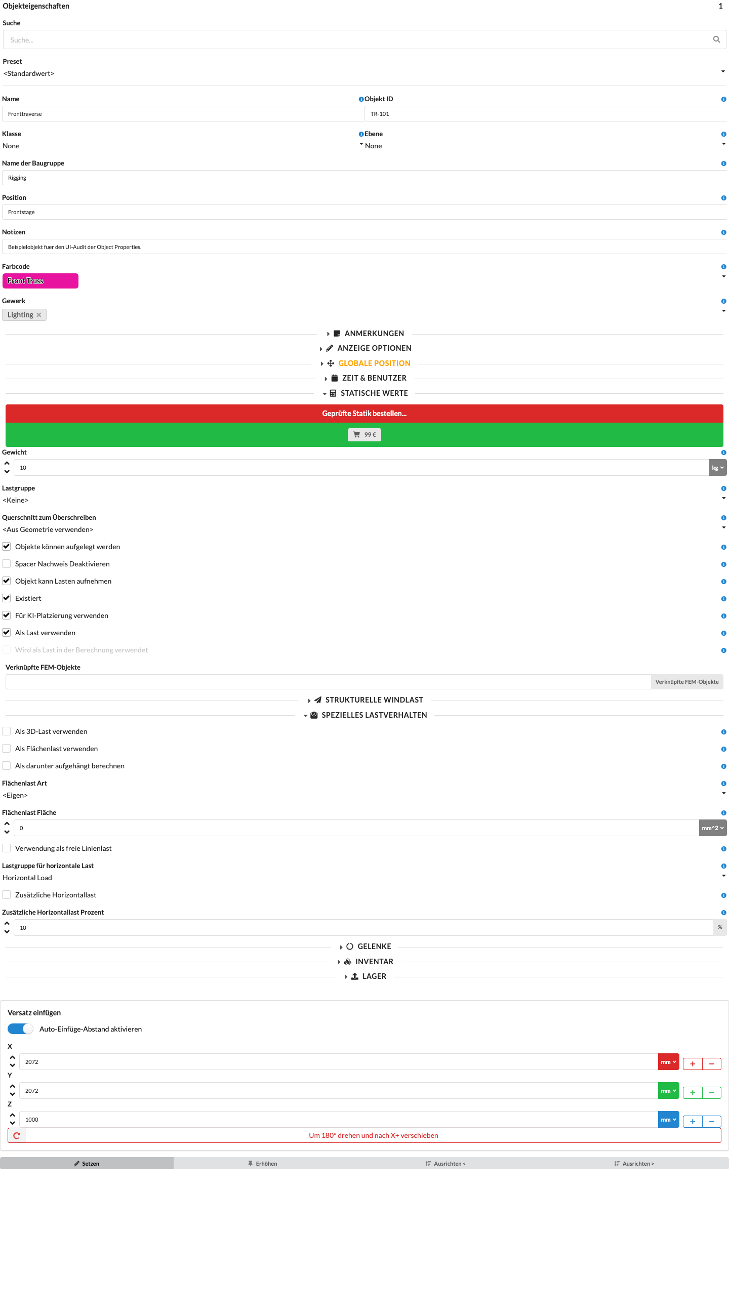
An area load requires a closed polygon geometry on the load object. Draw or create the polygon as geometry of the object or its symbol definition, enable Use as Area Load under Object Properties → Static Values → Special Load Behavior, and check Area Load Area. The area is calculated from the polygon; it is not a substitute value to enter manually. Position and orient the polygon so that load components can be transferred to the intended structural members. For a suspended area, Calculate as Suspended can enable assignment to the nearest structural member above. An area that is not connected or cannot transfer its load results in Area Load Not Assigned.
In CAD drawings, assign the layer or class to the Area Load load type under File → Settings → Structural Lines → Load Layers. The geometry must be a closed polygon on this layer; a layer name alone does not create an area. For AutoCAD/BricsCAD, PA-Area Load and 911-AREA_LOAD are designated as area load layers. In the SketchUp extension, create an area using Insert Area Load by placing at least three points on the structure and double-clicking to finish at the last point. Host-specific steps are in Load Layers, Load Geometry in AutoCAD/BricsCAD, Insert an Area Load in BricsCAD, and Insert an Area Load in SketchUp.
Area Load Type can apply an additional standard-based area load on top of the object's weight. Own does not add a standard flat-rate value. After drawing, check the displayed area; after calculation, check the load assignment and results. The current object configuration shows the switches and automatically determined area field:
A 3D load is intended for an object with spatial volume geometry. Enable Use as 3D Load when Production Assist should use the object's volume and its actual contact points with the supporting structure to distribute the weight. Unlike an area load, this method does not require a load polygon outline. The spatial distribution is determined separately using an FEM calculation. Check that the 3D body represents the real body and its connections appropriately.
Calculate as Suspended controls which structural member receives the load when the object is below the structure. The option assigns it to the nearest structural member above, but does not replace modeled suspension ropes. More examples and limitations are described in Area Load, 3D Load, and Suspended Load.
Automatic derivation does not replace checking the model. After drawing or making changes, check that Production Assist has detected and correctly assigned the expected structures, connections, loads, and supports. The drawing is the input; errors or missing geometry in it affect the generated structural model.
Wind loads also depend on the wind load area, wind model, location, and wind direction. The main settings are described below; for details about wind areas, load images, and location assumptions, see Understanding and Checking Wind Loads.
Commands for creating additional point, line, and wind loads are described under Rigging → Loads.
The Set Weight dialog opens from Fix on a Load Has No Weight error message. It changes the weight of the affected load objects; after correcting it, check that the value matches the real object. Causes and further steps are described under Error Messages and Troubleshooting.
A load group assigns loads to a shared load case. For example, this lets you apply different factors to dead load, imposed load, wind, or cable weight within a load combination, or exclude them entirely. Select the group for an object in Object Properties → Inventory → Load Group. Wind and horizontal loads can have their own load group fields; check these separately.
Manage groups in Load Groups under Navigation. There you can set the name, Load Factor, and Load Group Type. The group factor applies to the group's loads and is multiplied by the factor of the active load combination and, where applicable, the layer factor. A factor of 1 leaves the load value unchanged; 0 excludes the group from that combination.
The Static or Variable type identifies the load group in outputs such as the calculation report and DSTV export. It does not itself change the load magnitude in the internal calculation. Use the type according to the project requirements, and check the resulting combination of factors in the report. Assign objects to another load group before deleting a group. For details, see Load Groups in Navigation.
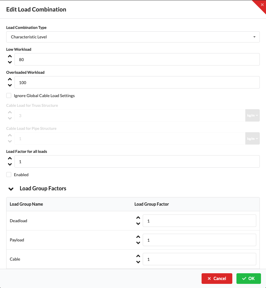
A load combination defines which load groups are considered together in a calculation case and the factors applied to their loads. In Navigation, under Load Combinations, select Add New Load Combination to create a combination. Change its name directly in the list, use the copy icon to duplicate it, or the red delete icon to remove an entry. The pencil icon opens Edit Load Combination. In that dialog, apply changes with OK or discard them with Cancel. In Production Assist, you separately choose which combination applies to the structural member and structure check, to supports, and to tipping and sliding. In a full calculation, Production Assist calculates these three purposes in parallel. For each purpose, the combination marked with the corresponding colored dot applies.
In a new drawing, Eurocode Ultimate Failure is selected by default for the structure, Usability for supports, and Tipping for tipping and sliding. Templates and existing drawings may use different selections. Settings is a separate settings profile, not a regular load combination. Before calculating, check the colored dots and factors in your drawing.
| Dot in the Load Combinations list | Calculation purpose | Default in a new drawing and displayed values |
|---|---|---|
| Green | General structural member and structure check | Eurocode Ultimate Failure (capacity, type Design Values). Section reactions in the Renderer follow this green selection. For a serviceability display, select Usability here. |
| Blue | Supports, including reactions at chain hoists and other supports | Usability (serviceability, type Characteristic Values). Support values in Object Properties → Support and the chain hoist forces derived from them use this blue selection. |
| Yellow | Tipping and sliding | Tipping (tipping and sliding stability, type Tipping Values). The calculation uses a separate selection and separate factors for this purpose. |
The types describe the kind of values for which the combination is intended. Characteristic Values are the characteristic starting values of the actions; in the default Usability combination, they use factor 1. Design Values include the partial safety factors used for the capacity check, which increase the characteristic loads for that check. In the shipped default combination Eurocode Ultimate Failure, these are 1.35 for Deadload, Cable, and Rigging, and 1.50 for Payload, Light, Audio, Video, Deco, Wind, and Horizontal Load. The default Tipping combination uses 1.0 for these groups and 1.2 for Wind and Horizontal Load. These are preset factors for a new drawing, not universally valid values: templates and project requirements can change them. Check the actual factors and use the requirements that apply to your project.
The values in the Renderer depend on which combination is active for each purpose. In particular, section reactions show the combination selected by the green dot; by default, these are design values from Eurocode Ultimate Failure, not automatically serviceability values. Support and chain hoist forces, on the other hand, follow the combination selected by the blue dot; by default, these are characteristic values from Usability. If you need serviceability values for section reactions, set the green dot to Usability and recalculate the model.
If you change an active combination or its factors, the results for its assigned calculation purpose change. The blue selection therefore changes support and chain hoist forces, the green selection changes structural and section reaction results, and the yellow selection changes the tipping and sliding check. Enable or disable additional combinations only when you know which result cases should appear in the report and evaluation.
For a load assigned to a load group and layer, the applied value is generally the load value multiplied by the load group's Load Factor, the combination's Load Factor for All Loads, the factor for that load group in the combination, and the layer factor. A factor of 1 leaves that contribution unchanged; 0 excludes it from the calculation case. The load group type Static/Variable identifies the group in reports and exports, but does not itself set the numerical factor value.
The Load Factor for All Loads is an additional multiplier for every load in that specific combination. For example, if the project requirement calls for a dynamic factor of 1.2 for support forces, you can enter 1.2 in the edit dialog for the active blue support combination. Production Assist then multiplies all loads in that support combination by this value; the calculated support and chain hoist forces are scaled accordingly. This does not automatically change the green structural combination or the yellow tipping combination. This additional factor is separate from the 1.2 for wind and horizontal loads in the default Tipping combination. It is a general load multiplier, not a dynamic time-history calculation. Support values scaled by 1.2 are no longer the unchanged characteristic starting values from the default setting. Use this factor only when it is specified for the particular setup.
If you are unsure which combination or factors apply to your check, do not change them. Load factors directly affect support reactions, section forces, deformations, and utilization. Confirm project-specific assumptions with the responsible specialist.
| Setting in “Edit Load Combination” | Effect and use |
|---|---|
| Load Combination Type | Identifies the combination as Characteristic Values, Design Values, or Tipping Values. The type determines which results the combination is intended for; the actual load values come from the configured factors. |
| Low Utilization and Overload | Set the percentage thresholds for the color-coded utilization display: green below the first threshold, yellow between the thresholds, and red from the overload threshold onward. They do not change loads or capacity values. |
| Load Factor for All Loads | Applies an additional multiplier to every load in this combination. The default value 1 leaves them unchanged. A specified dynamic factor can be entered here as a general multiplier; it applies only to this combination. |
| Load Group Factors | Multiply the loads in each group. In Eurocode Ultimate Failure, for example, the default drawing uses 1.35 for Deadload, Cable, and Rigging, and 1.50 for the listed variable groups. A factor of 0 excludes a group from this combination. Check the factors in your drawing. |
| Layer Factors | Multiply loads according to their layer. They change load values but do not determine whether an object is included in the calculation. Objects on hidden layers are also calculated by default; only the Calculate Visible Objects Only filter makes visibility a calculation criterion. If Use Layer Factors from Support Load Combination is enabled in Settings, the active support combination's layer factors apply to the other combinations instead. |
| Ignore Global Cable Load Settings | Allows custom cable allowances for this combination. If the option is disabled, the cable values from the Settings profile apply. |
| Cable Allowance for Trusses and Other Cross-Sections | Additional assumed cable or line load on trusses and other cross-sections when global cable values are not used. |
| Cable Allowance for Pipes | The corresponding cable allowance for pipes. Check the unit and assumption against the planned setup. |
Each of the three colored dots can point to a different load combination. This allows the same drawn load to use different factors in the structural, support, and tipping calculations. Enabled controls additional calculation cases; the colored dot determines which combination applies to the respective primary calculation purpose and its displayed results.
Load Combination Settings opens the Settings profile. It contains advanced settings that apply to the calculation as a whole, particularly the calculation model, wind, and ground. These values are distinct from the factors for an individual load combination.
These options affect the calculation model and verifications. If you are unsure what a setting does, do not change it without consulting the person responsible for the calculation.
| Setting in “Load Combination Settings” | Effect and use |
|---|---|
| Second-Order Calculation / ∆P Method | Calculates equilibrium on the deformed system. This means deformations affect internal forces and further deformation. When the option is off, equilibrium is calculated on the undeformed system, so deformations do not change the force distribution. A first-order calculation may be sufficient for simple cases where axial forces do not significantly affect deformation. For slender members or members subject to compression and bending, a second-order calculation is important for capturing stability effects such as P-∆ and buckling. It does not replace checking that the geometry, supports, cross-section, and verifications are modeled appropriately for the specific buckling case. |
| Calculate Internal Members | Switches from the simplified global centerline structure to the individual-member model using the internal members prepared in the symbol definition. The symbol geometry must contain internal structure for this. The models and their use cases are described in Global Structure and Internal Members. |
| Check for Cable Failures | Reports cables that are in compression in the calculation. Since cables only transfer tension, this indicates a problem in the cable system or an unsuitable system assumption. |
| Calculate Compensated Chain Shortening | Iteratively calculates individual chain shortenings so that the suspended system remains level despite deformation of the upper structure. The option works together with Chain Shortening Compensation at the individual supports; see Chain Shortening Settings. |
| Check the Interaction of Every Part of the Truss | Checks the combined stress from shear force and bending moment between the usual connector positions as well. This matters in the connector area because the truss force path is interrupted there, and the transition from the connector to the weld and chord tube may govern. Enabling this check is useful for a complete assessment of these locations. |
| Check Whether Spacers Can Be Installed Everywhere | Checks the spacer verification along the truss rather than only at the usual check points. Spacers can significantly affect the available capacity. This option is useful when their possible positions are not limited to the standard locations or when the entire truss length must be assessed. It checks possible locations; it does not add spacers to the drawing. |
| Deflection Limit, Deflection Limit 1/L, Deflection Limit for Layer, and Deflection Limit for Layer 1/L | Enable the deflection verification and set a global limit, with different limits for individual layers if needed. An entry such as 1/200 means the ratio L/200. This is an example, not a generally valid limit: use the requirement in the applicable standard or project specification. If the limit is exceeded, Production Assist reports a deflection issue; the limit changes neither the geometry nor the member's strength. |
| Use Load Measurement for Calculation | Includes the current measurement from an active load cell assigned to a support in the calculation. Production Assist uses the difference between the calculated support force and the measured value as a load change, then assesses the model in this measured load state. The other drawn loads remain part of the model. Prerequisites and assignment are described in Connect Load Cells and Check Measurements. |
| Verification Scripts | Selects additional project-specific or user-specific check scripts. For example, these scripts check project-specific conditions in addition to the built-in structural verifications. See Automatic Checks with Scripts for details about their management and operation. |
| Use Layer Factors from Support Load Combination | Uses the active support load combination's layer factors for the other calculations. Without this option, layer factors are generally maintained separately for each load combination. This saves setup work when the structural, support, and tipping calculations should use the same weighting for each layer. Disable it if one of the other combinations needs its own layer factors. |
| Disable Cable Load for Layer / Disable Cable Load | Turns off the automatically applied cable allowance for an individual layer. Production Assist can distribute this additional load across suitable trusses and other cross-sections. This may be unsuitable for pre-rig layers, for example, or could double-count a cable load that is already modeled individually. The option disables only the automatic allowance on that layer; drawn load objects remain effective. |
Spring joints: Under Object Properties → Joints, linear and piecewise-linear connection springs can be defined for individual force or moment components. These springs are solved iteratively, independently of the second-order calculation switch. When the ∆P method is enabled, the calculation additionally accounts for the influence of axial forces. The cable-force check switch does not turn off the ∆P iteration. If the equilibrium iteration does not converge, the run ends with an error. Tension and compression members are disabled when the force direction is impermissible and can carry load again if the load changes. The stability check uses the actual spring stiffnesses and checks both the member connections and the combined system. Auxiliary stiffnesses for the iteration do not conceal instability in open clearance ranges. The accuracy of a buckling calculation still depends on the subdivision into calculation elements; more display points on a result curve do not refine this mesh. Rotations in the section forces refer to the local member axes; a concentrated moment acts according to its local axis and sign.
The Layher K2000+ cross-section presets automatically assign suitable connection springs to the stored O/U ledgers and the double wedge-head coupler. Inherited connections use the cross-section; explicit geometry or object settings take precedence. For ledgers shorter than 600 mm, the rotational components are released. After changing a cross-section, check the connection assumptions and the required substitute-model geometry. Existing drawings that previously used inherited connections for these standard profiles also use the new presets.
Section force diagrams are recovered from member displacements and the applied loads. At a point load, the values immediately before and after the load are retained separately. Deformation remains continuous there; shear force or moment can jump according to the applied force or moment. The deformation at a spring-connected member end can differ from the displacement or rotation of its calculation node.
In a suspended structure, the upper trusses can deflect under load. Without compensated chain shortening, the calculation uses the drawn chain lengths and any existing manual chain shortenings; as a result, deformation of the upper truss also changes the height and load distribution of the structure suspended below it. With Calculate Compensated Chain Shortening, Production Assist iteratively calculates the required shortening or lengthening of the involved chain hoists. This levels the system in the calculation instead of passing the upper structure's deflection unchanged to the lower structure. The suspension points are considered together across the system, much like balancing a mobile: adjusting one chain can affect the required adjustment of the other chains. The option is global; Chain Shortening Compensation must also be enabled at the individual supports. The calculated values are assigned to the chain-shortening properties of the affected supports. After the calculation, check these values and the resulting geometry, especially for pre-rig and multi-level suspended systems. The function balances the system but does not guarantee less deflection at every local point.
The truss force path changes at a truss connector. Shear force and bending moment can act together on the connector, its weld, and the connection to the chord tube. This local interaction can govern capacity. Without Check the Interaction of Every Part of the Truss, the regular check points are at the designated connector positions. With the option enabled, interaction is examined at every calculation point along the truss, so the check does not depend on the existing segmentation or standard positions. This does not mean that Production Assist inserts additional connectors into the drawing.
Spacers can significantly reduce a truss's capacity and make the governing verification more demanding. Check Whether Spacers Can Be Installed Everywhere runs the spacer verification along the entire truss, including locations where no spacer is modeled in the drawing. Use this setting when you need to ensure that the truss has sufficient capacity even if a spacer could be positioned anywhere along its length. The object-specific property Disable Spacer Verification can turn off the verification for an individual object. For truss cross-sections with bracings, the property note says this exception may be necessary to calculate the full capacity; it does not affect other cross-sections.
When Use Load Measurement for Calculation is active, a running connection must provide current values and the load cell must be assigned to the correct support. For a pre-rig with load cells on the chain hoists, Production Assist can use the difference between the calculated support force and the measured value as an additional load change and verify the truss in this measured load state. This lets you check whether the actual load distribution changes utilization or the verification compared with the originally assumed loads. Without an active connection or a suitable assignment, no current measurement is available for this calculation. The connection, cell ID, and measurement display are described in Connect Load Cells and Check Measurements.
The Verification Scripts selection adds available automatic JavaScript checks to the built-in structural verifications. In the Settings profile, select the check scripts relevant to the document. Selected scripts from the active structural and support combinations are also considered. These checks can, for example, verify project-specific properties or requirements that are not covered by a built-in standard verification. Automatic Checks with Scripts explains which checks are available and how they are maintained.
Wind parameters are maintained centrally in the Settings profile. The wind load type selects the calculation model and can change other assumptions, such as base pressure or horizontal load. The country, wind zone, and terrain category affect location-specific values. Wind speed and wind pressure are linked; changing one value updates the other.
| Setting | Effect and use |
|---|---|
| Wind Load Type, Country, Wind Load Zone, Terrain Category | Determine the wind model and location assumptions. Choose the model that applies to the location and operating condition. The available types and their prerequisites are explained in Choose a Wind Load Type and Location. |
| Wind Load Approach | Specifies how wind factors are determined by height, for example using fixed heights or an exponent. The input fields change depending on the selected method. Check the displayed factors against the applicable wind model. |
| Wind Direction | Sets the wind direction angle relative to the global X axis when not all directions are calculated. |
| Wind Speed and Wind Pressure | Display or set the wind model's base values. They are linked; check both after a manual change. |
| Building Height | Reference height for the wind profile and associated factors. The calculation uses the geometry of each structural part to determine its actual height. |
| Temporary Use Factor | Accounts for a reduction when the applicable rules allow it for temporary structures. Use only as specified by the applicable standard or project specification. |
| Wind Load Factors | Describe how wind load varies with height. Depending on the wind model, the factor is set at fixed heights or with a power function relative to the building height. Check the curve and its inputs against the applicable wind model; see Choose a Wind Load Type and Location for details. |
| Wind Load on Roof Downwards | Selects the downward pressure branch for roof wind loads. When the option is off, the suction or uplift branch is used. Check the direction together with the roof geometry and wind load images. |
| Calculate All Wind Directions at the Same Time | Calculates multiple directions over 360°. Set the angle increment in File → Settings → App → Angle for Wind Load from Multiple Directions. A smaller increment increases calculation time. |
| Use Second Wind Pressure | Enables a second wind configuration with its own parameters, for example for a different operating condition. Its associated values are available only when the second configuration is enabled. |
| Horizontal Load from Total Load and percentage | Adds a horizontal load as a proportion of the total vertical load. The percentage applies only when the option is enabled. Use it when the applicable requirement calls for such a horizontal proportion. |
Which objects receive wind load is also determined by wind load layers and object options. Check the areas, wind CF values, and wind load image results separately. Full details about wind areas, profiles, direction, and load images are provided in Understand and Check Wind Loads.
| Setting in "Load Combination Settings" | Effect and use |
|---|---|
| Ground Load Capacity | Specifies the permitted ground load per area and is used for the ground load check. For automatically generated ground supports, Production Assist also uses this value for the vertical utilization display and converts it to a reference area of 1 m². This does not check the actual contact area or the permitted point load of an individual Ground Support foot. |
| Use Ground as Support | Automatically creates supports where calculable structural members intersect the ground plane. This means you do not need to place individual Ground Support Attachments in the drawing at those points. The generated supports act in the calculation and provide reactions in X, Y, and Z. |
| Ground Height | Sets the height of a horizontal ground plane. When Use Ground as Support is enabled, an automatic support is created at each point where this plane intersects a calculable structural member. Check that the height matches the actual ground or contact surface. In the 3D renderer, use Show floor support height to display the plane and Move to shift it vertically; releasing the handle changes the same ground height in the Settings profile, not just its display. |
| Use Ground Friction and Ground Friction Value | Enables the sliding friction check and sets its coefficient of friction. Production Assist compares the horizontal resultant of the X and Y reactions with the frictional resistance from the vertical support reaction and friction value: √(X² + Y²) ≤ Friction Value × Z. The check applies only when the vertical reaction is compressive. Use a value that matches the actual ground and support material pair. |
| Allow Uplifting Force on Ground | Specifies whether a ground support can also carry tension when the structure tends to lift. Enable this only if the support is actually anchored or bolted to the ground and can transfer tension. For a freestanding foot, leave the option off; the support is then released when the reaction is upward. |
Use Use Ground as Support to model a continuous, horizontal ground plane as a support. Production Assist searches the structural model for members that intersect this plane and automatically creates supports there. Nearby intersection points are not created as multiple, almost overlapping ground supports. This is especially useful when there are many posts or ground contact points: you do not need to place a Ground Support Attachment at each one. A manual Ground Support Attachment remains useful when a support is not at the shared ground height or when you need custom support properties and an explicit connection in the drawing. Do not also place a manual support at a point already modeled by an automatically generated ground support; both supports could hold the system twice.
Set up the supports as follows:
Automatically generated supports can also be used in the Calculate Ballast workflow. The ballast calculation uses the support reactions to determine the required additional ballast and, when ground friction is enabled, accounts for the assumed horizontal friction effect. See Calculate Ballast for the workflow and how to check the results. Ground supports, the ground load check, and the ballast calculation are different parts of the model: an automatic ground support represents the contact point for structural analysis, but not an actual contact area, bolted connection, or on-site installation. For individual support objects and their properties, see Ground Support Attachments.
Under File → Settings → App → Structural Calculation Settings, there are other options for calculation display and behavior. These include mesh resolution and the angle increment for multiple wind directions, as well as showing or hiding point load and line load labels. Use Hide load table explanation in structural reports to hide the automatically generated explanatory text below load summaries in calculation reports; the load tables remain. The Show Structural Errors, Utilization Display, Show Ground Supports, and Show Labels for Automatically Generated Supports settings control the renderer display; they do not change the applied loads or the calculation itself. See Settings and Renderer Settings for details about these options.
After every calculation, check not only the messages and tables but also the structural behavior in the 3D Renderer. The views above show the idealized structure, section reactions, support reactions, and the deformed utilization display. Check whether the detected structural members match the drawing, whether the deformation shape and reactions are plausible, and whether the utilization values are within the limits. A green display alone does not replace checking the numerical values and verifications.
Open Rigging → Show Calculation Summary... to review the status, errors, loads, wind loads, and verifications together. The summary updates the calculation data when opened. Zoom and Select jumps to the relevant object. In addition to the status display, check the errors and result groups; a green overall status alone does not confirm that all expected parts of the model are included.
The summary includes, among other things, loads with their load group and layer, wind forces, support reactions, and verifications for rigging hardware, drops, bridles, cross-sections, and ground supports. For wind loads, the image icons open the corresponding wind load images. Check the displayed direction and distribution against the geometry. The tables and status displays are explained in Check Calculation Results.
For bridles with assigned components, strand utilization and the bridle verification use the lowest complete capacity among ropes, shackles, chains, and basket components. The material set and rope cross-section are selected jointly for all strands, including the basket and drop. The selected rope cross-section, end fitting efficiency, and rope safety factor limit the rope value; missing component ratings do not provide a complete strand capacity. The standard sets have reference WLLs for shackles, STAC, and chain shorteners; the native standard 8 mm rope definition also includes its mass per length. Missing WLLs for older standard hardware are added when loading. Without assigned components, the entered support capacity continues to apply. Automatic component assignment determines the connection point height above the fixed lower load point from a single rope element of the first strand, including the shackle and basket. The other strands and the drop are fitted to this height; unavoidable length differences remain visible. Changing the fixed length of the first rope can therefore change the geometry and forces. Check the inputs and missing values in the Bridle View, and recalculate after making changes. When applying the bridle component preview or using automatic component assignment, the complete component weight, including basket and drop, is transferred to the object weight used for load modeling. The preview alone does not change it. If component masses are missing or component assignments are incomplete, the previous object weight is retained; the Bridle View marks the known subtotal as incomplete. Repeated fitting does not add extra weight. Update the structural calculation after a weight change.
After a successful calculation, Object Properties → Support shows Roof Force and Hook Force for suitable supports. On the calculation result object, under Object Properties → Section Reactions, you can select additional section forces and deformations to display. For instructions on checking the force flow, see Check Connections in the Structural System. For a professional assessment of the integrated calculation and where to get support, see Professional Assessment and Support.
Use File → Export Calculation Report as PDF... after the calculation to create a PDF structural calculation report. Choose Simple Export for a report based on the selected standard result groups, or Advanced Export to assemble your own sections, text, and result placeholders. The detailed guide Create and Design a Calculation Report explains both methods, templates, and the report structure. The report documents the selected inputs and results; it does not replace a professional review or a verified structural calculation.
The error list shows messages for the current model. Select a message to find the affected object, then first correct its geometry, cross-section, connection, load, or support. Recalculate the model afterward. Explanations of support, load, cross-section, and rope errors are available under Error Messages and Troubleshooting; Errors in Navigation explains how to use the error list.
For ground-support systems, Rigging → Special Operations → Calculate Ballast can determine the required ballast from the support reactions. Prerequisites and how to interpret the result are described under Calculate Ballast.
Use Rigging → Arena → Save Structural Results as Maximum to save selected calculation results as comparison values in the structural elements. This can be useful, for example, for imported DSTV data whose load limits should be taken into account in later calculations. Check the saved values in the symbol definition's Edit Mode before using them as comparison values. The Mt and Mby values are not saved reliably in the current version.
The Structural Wizard provides selection cards for wind loads, area loads, ballast, and ground loads. Open it from Rigging → Show Structural Wizards ... or from the Load Combinations tab. Making a selection does not start a calculation. Then check the resulting values in the load combination settings and on the affected objects; Choose a Wind Load Type and Location explains the complete wind parameters and prerequisites.
The Help → Show Truss Calculator... dialog calculates cross-section values for a simplified profile geometry and entered load cases. Use the results as a calculation aid and check all inputs; the dialog does not replace the static calculation of a fully modeled system or an externally reviewed structural calculation.