

Production Assist is available as a plug-in for BricsCAD. The plug-in integrates directly into BricsCAD and offers the same range of functions as the desktop app and the other plug-ins.
The main task of the plug-in is to integrate BricsCAD into the Production Assist workflow. This allows you to use load values, calculation results, and internal forces directly during construction in your usual CAD environment.
Production Assist currently supports the following BricsCAD versions:
You can see which version is installed with the about command.
Each BricsCAD version requires its own plug-in file. An installed Production Assist desktop app is always required.
If you install the plug-in via the desktop app, the matching host application, i.e. BricsCAD, must also already be installed.
For example, BricsCAD 2026 on Windows requires the file libProductionAssistBRX26.brx.
For example, BricsCAD 2026 on macOS requires the file libProductionAssistBRX26.mrx.
Limitations
In BricsCAD for macOS, the real-time integration only works after changing the view.
On Windows and macOS, you must bring BricsCAD to the foreground so that changes from the Production Assist desktop app become visible.
Attention: For Production Assist to work correctly, both the desktop app and the plug-in must be installed. All required support files such as cross sections and templates are included with the installation.
There are two installation methods:
We recommend installation via the desktop app because it automatically checks for updates when the program starts. Manual installation does not include automatic update checks.
The following applies to installation via the desktop app:
The Production Assist desktop app must be installed. Download it from https://www.production-assist.com/download and install it.
BricsCAD must be installed. Bricsys describes the installation at https://www.bricsys.com/de-de/bricscad-download.
Start the Production Assist desktop app and run the menu command Help → Install BricsCAD Plugin....
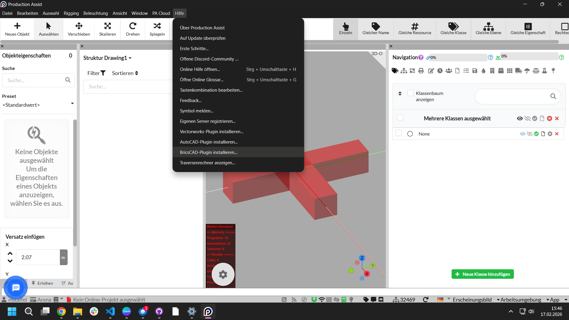
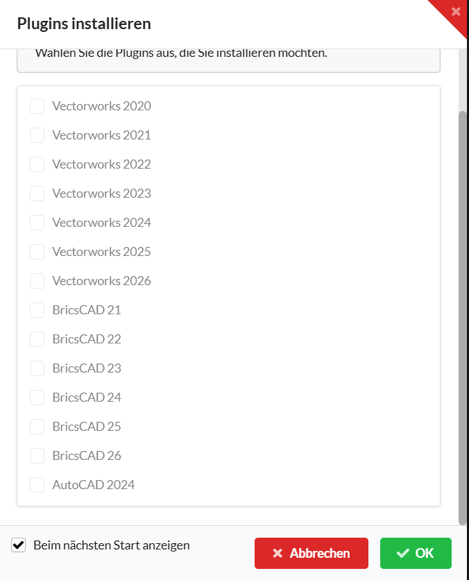
This menu command opens a dialog where you can choose the plug-ins available for installation. Only plug-ins whose host application is installed can be selected. For example, if BricsCAD 2024 is installed, the plug-in for BricsCAD 2024 can also be installed.
After successful installation, the plug-in is stored in the following folder. The path depends on the installed BricsCAD version. YY stands for the version number, for example 26 for BricsCAD 2026.
Windows: %appdata%/productionassist/brx_plugin/BRXYY/libProductionAssistBRX_YY.brx
macOS: /Users/BENUTZERNAME/Library/Application Support/productionassist/brx_plugin/BRXYY/libProductionAssistBRX_YY.mrx
The Production Assist Library is stored at the following path:
Windows: %appdata%/productionassist/brx_plugin/ProductionAssistLibrary
macOS: /Users/BENUTZERNAME/Library/Application Support/productionassist/brx_plugin/ProductionAssistLibrary
Example for BricsCAD 2026
Plug-in:
- Windows:
%appdata%/productionassist/brx_plugin/BRX26/libProductionAssistBRX_26.brxC:/Benutzer/Kontoname/AppData/Roaming/productionassist/brx_plugin/BRX26/libProductionAssistBRX_26.brx- macOS:
/Users/BENUTZERNAME/Library/Application Support/productionassist/brx_plugin/BRX26/libProductionAssistBRX_26.mrx
The ProductionAssistLibrary folder is located inside the brx_plugin folder.
Info: You will need this path in the section Integrating the Production Assist Library in BricsCAD.
The advantage of installing via the app is that Production Assist is automatically kept up to date.
The ZIP file contains several folders for the supported BricsCAD versions as well as the Production Assist Library.
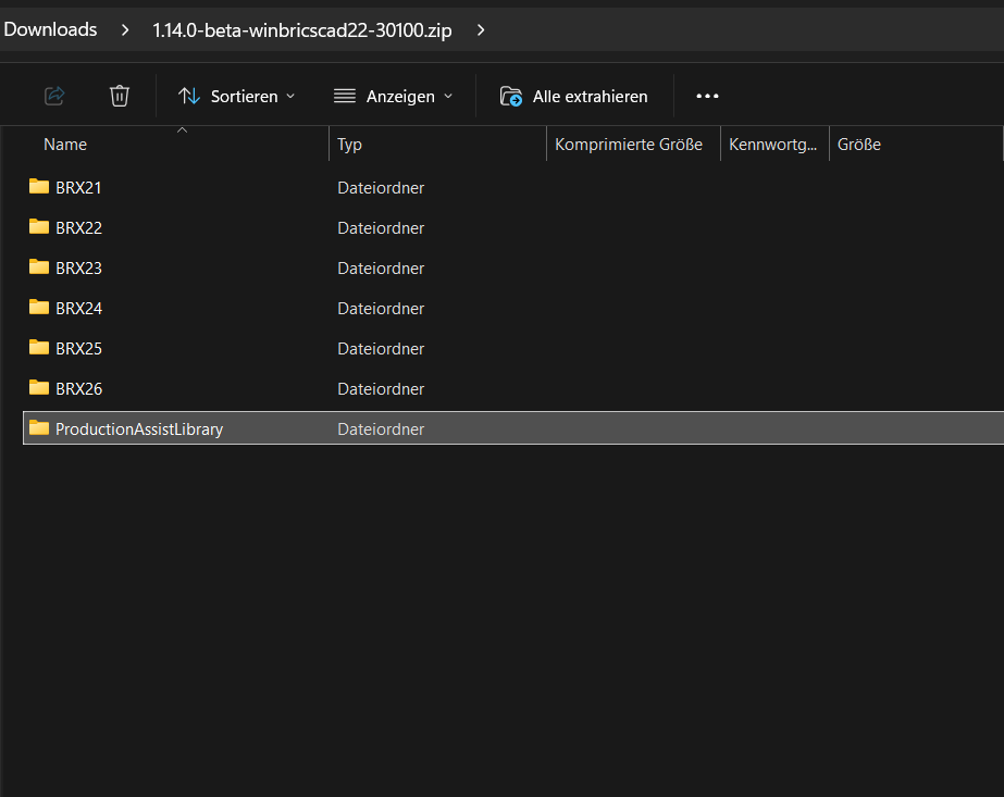
The following mapping applies:
| Abbreviation | BricsCAD version |
|---|---|
| BRX26 | BricsCAD 26 |
| BRX25 | BricsCAD 25 |
| BRX24 | BricsCAD 24 |
| BRX23 | BricsCAD 23 |
| BRX22 | BricsCAD 22 |
| BRX21 | BricsCAD 21 |
Installation for Windows
Save the extracted files in any local location.
Installation for macOS
Save the extracted files in any local location.
Attention: If possible, do not use a network folder to avoid performance problems.
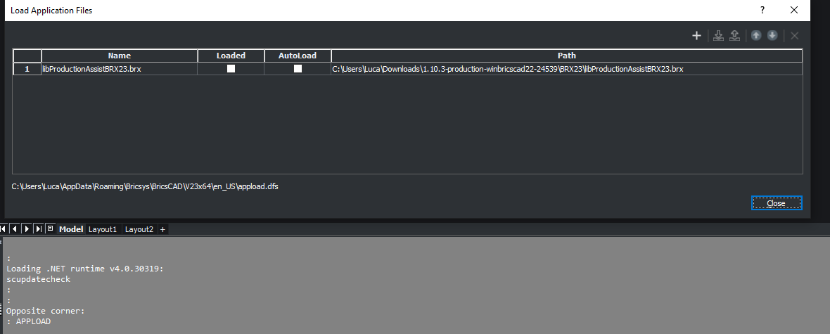
To use Production Assist in BricsCAD, it must be loaded with the APPLOAD command.
Enter APPLOAD in the command line. The following dialog appears:
For example:
libProductionAssistBRX25.brx for BricsCAD 2025 on WindowslibProductionAssistBRX25.mrx for BricsCAD 2025 on macOSNote: If
Autoloadis enabled, the Production Assist plug-in is loaded automatically every time BricsCAD starts.
Otherwise, you must run APPLOAD manually.
You can also disable the plug-in again via the same dialog. To do so, clear the checkbox at AUTO or click Unload selected Application on the right. You can completely remove the entry with the X on the right side.
When the plug-in has been loaded successfully, the command line shows the corresponding status:
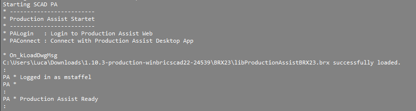
The BricsCAD command line confirms the user logged into the Production Assist desktop app and the status Ready.
For structural calculations, the blocks used require certain information. This data is already included in the supplied Production Assist Library.
To get started, we recommend the supplied Production Assist Library because it is already prepared for use with Production Assist. For your own blocks, materials, and customized workflows, see the later section Customizing the Production Assist Library.
To access the blocks from the Library in BricsCAD, the Library must be integrated once.
Open the context menu with a right-click in the right sidebar and activate the Library area under PANELS.
The Library area now appears on the left. Open the Manage Library entry there via the three-dot menu. The Settings window opens.
Under library directory path, select the storage location from the plug-in installation. The folder you need is called ProductionAssistLibrary.
For a correct block preview, click Generate thumbnails in the three-dot menu of the Library. This creates previews for the imported symbols and blocks.
When inserting blocks into BricsCAD, specify scaling and rotation if needed. The default value for scaling is X = 1 and Y = 1. If you do not enter a rotation value, 0 degrees is used.
Add components from the Production Assist Library to your model, for example trusses and chains.
Start PA synchronization to connect your model with Production Assist.
Add loads to your structures using the load tools.
Run the calculation in the Production Assist palette.
Display the results via the layers to check forces, errors, and analysis data directly in BricsCAD.
This guide walks you through a simple truss construction with two chains and your first calculation.
APPLOAD.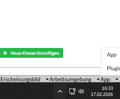
As soon as Plugin mode is active, the Production Assist desktop app automatically connects to the running BricsCAD instance. It then serves as the user interface for settings, Load Combinations, reference values, and the creation of reports and plans. The calculation itself is carried out by the BricsCAD plug-in.
Attention: Some display parameters for BricsCAD are controlled in the Production Assist desktop app. This includes, for example, the
ProductionAssist_*_Textlayers. These are made visible via theErgebnisse in 3D anzeigenoption.

Panels > Library in BricsCAD.
h30v-l200-3q.
With the COPY command:
Via drag and drop and the Shift key:
Attention: A truss cannot snap to its own copy. If necessary, first create an additional working copy of the block.
CMF.For easier alignment and snapping, you can temporarily hide unnecessary layers.
Sidebar > LAYER in BricsCAD.
100 kg.
You have now completed your first structural calculation in BricsCAD with Production Assist.
By default, your drawing data is saved in DWG format. Geometry, block definitions, block references, and the attributes contained in the blocks are therefore stored directly in the DWG. Wherever possible, Production Assist writes project-related information into the block definitions and their attributes.
In addition, when the option is enabled, Production Assist creates a separate LRWX file next to the DWG. The LRWX file contains all project-specific information that cannot be fully or meaningfully represented in block definitions and attributes, for example Load Combinations, complex mappings, or PA settings.
The creation of the LRWX file can be disabled in the settings. If saving the LRWX file is turned off, only the information stored directly in the DWG remains. LRWX-specific data is then lost or is not passed along with the drawing.
Recommendation: Enable saving of the LRWX file and keep it together with the DWG so that project-relevant settings, especially Load Combinations and other PA-specific data that cannot be stored in attributes, are not lost.
| Option | Advantages | Disadvantages |
|---|---|---|
Save LRWX next to DWG | Production Assist-specific settings and calculation results are saved separately from the drawing. Complex PA data is retained even when it cannot be fully represented in block attributes. The file can be useful for support exports, handover, and restoring PA project states. | In addition to the DWG, another file must be stored and kept with the project. If the LRWX file is missing or not copied, Production Assist-specific information will be missing even though the drawing exists. |
In practice, you rarely plan event technology on an empty drawing. Most of the time, you work on the basis of existing documents such as venue plans, customer drawings, stage layouts, or approval plans. Production Assist adds rigging-relevant objects such as trusses, hoists, loads, and calculation results to this planning context.
This section shows which file types typically play a role in this workflow and what they are used for.
DWG/DXF
DWG and DXF files are the most important working basis in BricsCAD. You will often receive floor plans, existing plans, or planning states in one of these formats and use them as the basis for your further work with Production Assist.
You then insert your trusses, hoists, loads, and other Production Assist objects into these existing CAD documents. This keeps the structural planning within the spatial and organizational context of the project.
Production Assist works with normal blocks and DWG data within the drawing. No proxy objects or special formats are introduced into the DWG that would make collaboration with other parties more difficult.
This means: anyone who receives this DWG file can continue working with it directly. Changes to geometry, blocks, or attributes remain regular DWG changes and can later be taken into account again by Production Assist when the file is re-read.
PDF documents
In addition, PDF files are often used in projects, for example as customer approvals, occupancy plans, rigging specifications, or reference drawings. Such documents usually serve as visual orientation or a coordination basis, even though they do not contain the same editable geometry as a DWG file.
MVR
MVR (My Virtual Rig) is used when data from a stage setup needs to be exchanged between CAD programs, visualizers, lighting consoles, or similar tools. This allows parametric and geometric information to be transferred between different programs.
MVR complements other formats such as GDTF and is particularly useful when you want to pass planning data consistently across multiple systems.
For the export and handover of a project, you must distinguish between two different data areas:
LRWX file with settings, mappings, and calculation results, as far as these are not fully stored in the DWG.Special feature: DWG workflow and compatibility
Production Assist does not change the normal DWG workflow. The blocks used in the drawing remain regular DWG blocks; no proxy objects or proprietary extensions are written into the DWG that would make it unusable in other CAD programs. You can pass a DWG on 1:1 to colleagues or to users of other CAD programs. They can open and edit the file even without Production Assist installed.
The prerequisite for loss-free return to Production Assist is that the relevant block definitions remain preserved in the DWG. If the corresponding LRWX file is also supplied and the recipient also has Production Assist, the PA-specific information is loaded automatically from the LRWX when the file is opened.
Important: If DWG and LRWX are not handed over together, LRWX-specific settings and results are lost or unavailable to the recipient. Therefore, for a complete handover between Production Assist workstations, always provide both the DWG and the corresponding LRWX.
For complete archiving or handover of a project, you should include at least the following files together in one archive:The following subsections describe how attributes, layers, and result data are exchanged between BricsCAD and Production Assist.
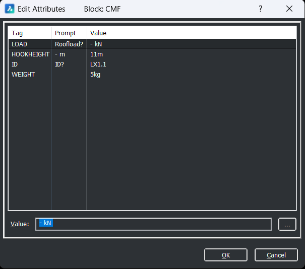
The display and data exchange of calculation results between Production Assist and the BricsCAD drawing takes place primarily through block attributes. Attributes are created in the block definition (Attribute Definition). When the block is inserted, the attribute values become part of the block reference (instance) and contain the specific measured values or results.
The most important standard attributes, their function, and their typical storage location are listed below.
| Attribute | Meaning | Typical use | Storage location / display |
|---|---|---|---|
Load | Calculated load or hook force of the hoist component | Is written back by Production Assist into the hoist component and can be checked in BricsCAD | Block attribute of the block reference; visible in Edit Attributes and in the OIP |
Hoist ID | Unique identifier of the motor or chain hoist | Used for unambiguous assignment in the drawing, calculation, and report | Block attribute of the block reference; visible in Edit Attributes and in the OIP |
Weight | Dead weight of the block or entered load | Used for load assumptions, load definition, and calculation | Block attribute of the block reference; visible in Edit Attributes and in the OIP |
Hook Height | Height of the hook or geometric information of the hoist component | Relevant for the position and calculation of suspension points | Block attribute of the block reference; visible in Edit Attributes and in the OIP |
+/-Force X | Force component in the X direction | Used for point forces or calculated forces | Block attribute; visible in the attribute dialog or in mapped properties |
+/-Force Y | Force component in the Y direction | Used for point forces or calculated forces | Block attribute; visible in the attribute dialog or in mapped properties |
+/-Force Z | Force component in the Z direction | Used for point forces or calculated forces | Block attribute; visible in the attribute dialog or in mapped properties |
The following illustration shows the editing of these attributes in the BricsCAD attribute dialog.
The following illustration shows the same attributes in the BricsCAD OIP (Object Info Palette).
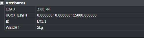
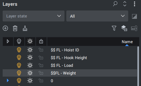
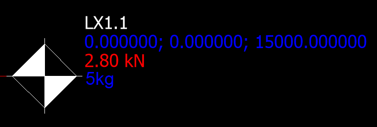
Using the CMF hoist component as an example, layers such as $ FL - Load, $ FL - Weight, $ FL - Hoist ID, and $ FL - Hook Height determine which additional information is displayed. The block itself remains visible; only the displayed values change depending on the active layer.
The values themselves remain stored in the block attributes.
Further attribute mappings and extensions are described in the section Property Map: Filling attributes in BricsCAD.
Production Assist synchronizes block attributes bidirectionally with the BricsCAD drawing as long as PA synchronization is active for the respective drawing. This means:
Important notes and examples:
Start PA synchronization) and the desktop app must be connected to the BricsCAD instance. Without active synchronization, no data exchange takes place.Load of a chain contains the load calculated by Production Assist. If Load is changed in BricsCAD, Production Assist overwrites this value again during the next calculation.Hoist ID / ID is used for the unique identification of lifting devices; changes are also synchronized and are important for assignments in reports.Weight is defined as an attribute in many blocks and describes the block weight. It is bidirectional, so a change in BricsCAD affects the calculation in PA.Additional standard attributes, hook parameters, and group assignments are described in the section Property Map: Filling attributes in BricsCAD and in the related subsections.
The definition of which actions and loads are to be calculated by Production Assist is made through the organization of drawing objects in layers. In BricsCAD, these layers clearly define both the structure of the load-bearing system and the position and type of the loads. Typical layer tasks are:
002-TRUSS_WIRE, 004-TRUSS_TUBE)PA-Point Force, PA-Line Load, PA-Area Load)902-SCAD_SUPPORT, 910-LAYHER_Support)003-TRUSS_SNAP, 900-SCAD_MAGNETS)Be sure to use layer names consistently. Production Assist interprets and maps geometry and load information based on these layers. If you create your own layers, assign them to the corresponding PA mappings in the settings so that automatic recognition and calculation work correctly.
The following layers contain the DWG parameters:
| Layer Name | Description |
|---|---|
| $ FL - Load | Hoist attribute: force at the upper hook (for example resulting tensile force) |
| $ FL - Weight | Hoist attribute: weight (for example in kg) |
| $ FL - Hoist ID | Hoist attribute: identification number (ID) |
| $ FL - Hook Height | Hoist attributes: upper hook offset X; upper hook offset Y; upper hook height |
| 0 | BricsCAD default layer |
| 002-TRUSS_WIRE | Truss geometry: chord tubes and bracings as lines |
| 003-TRUSS_SNAP | Bounding box / contour of the block (centered over the chord tube); used for snapping |
| 004-TRUSS_TUBE | 3D geometry of chord tubes and bracings |
| 900-SCAD_MAGNETS | Connection points and assigned connectors (magnets) |
| 902-SCAD_SUPPORT | Drops, ropes, and other support elements |
| 910-LAYHER_Support | Points for supports of the Ground Support Attachment; contains load information |
| 911-TRUSS_CENTER_STATIC | Center line of the blocks; basis for a continuous structure; color defines the cross-section |
| PA-Area Load | Area loads: closed polylines; weight stored in the block attribute Weight |
| PA-Line Load | Line loads: lines/polylines; weight stored in the block attribute Weight |
| PA-Point Force | Point forces: points; forces stored in attributes +/-Force X/Y/Z |
| PA-Wind Load | Wind loads: closed polylines for describing wind areas |
Cross-sections, calculation results, and section reactions are displayed in dedicated result layers. Production Assist creates these layers automatically and uses the prefix ProductionAssist_ followed by the respective value, for example ProductionAssist_Dx.
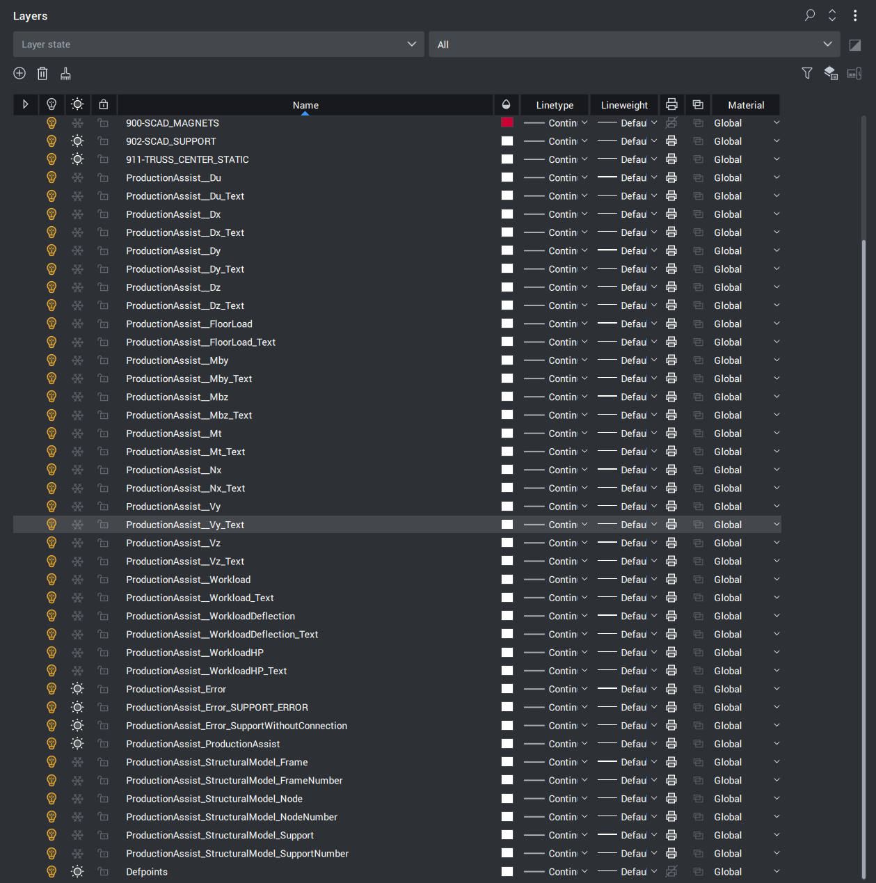
Important notes and conventions:
An explanation of the individual values can also be found under Navigation -> Influence Lines.
Influence Lines visualize specific result values along an element. Production Assist shows both layer-based displays and point/text values. In short:
ProductionAssist_Dx, ProductionAssist_Vy, etc.). Local maxima and text labels are displayed additionally on the corresponding ..._Text layers (for example ProductionAssist_Dx_Text).Workload*), and error indicators (ProductionAssist_Error*).| Layer Name | Description | Required interpretation for |
|---|---|---|
| ProductionAssist_Du | Shows the combined deformed shape. This is the vector addition of Dx, Dy, and Dz. | Overall assessment of the spatial deformation of a structure |
| ProductionAssist_Du_Text | Shows the local maxima of the combined deformed shape. | Quickly locating the greatest total deformations |
| ProductionAssist_Dx | Shows deformation in the X direction | Checking deformation in the longitudinal direction of the model |
| ProductionAssist_Dx_Text | Shows the local maxima of deformation in the X direction | Identifying critical extreme values in the X direction |
| ProductionAssist_Dy | Shows deformation in the Y direction | Checking lateral deformation in the Y direction |
| ProductionAssist_Dy_Text | Shows the local maxima of deformation in the Y direction | Identifying critical extreme values in the Y direction |
| ProductionAssist_Dz | Shows deformation in the Z direction | Checking vertical deformation or deflection |
| ProductionAssist_Dz_Text | Shows the local maxima of deformation in the Z direction | Identifying critical extreme values in the Z direction |
| ProductionAssist_FloorLoad | Shows floor load | Assessing load transfer to the floor and substructure |
| ProductionAssist_FloorLoad_Text | Shows the local maxima of the floor load | Locating local peak floor-load values |
| ProductionAssist_Mby | Shows bending about the Y axis | Assessing the bending moment about the local Y axis |
| ProductionAssist_Mby_Text | Shows the local maxima of bending about the Y axis | Identifying maximum bending moments about Y |
| ProductionAssist_Mbz | Shows bending about the Z axis | Assessing the bending moment about the local Z axis |
| ProductionAssist_Mbz_Text | Shows the local maxima of bending about the Z axis | Identifying maximum bending moments about Z |
| ProductionAssist_Mt | Shows torsion about the X axis | Assessing twisting and torsional loading |
| ProductionAssist_Mt_Text | Shows the local maxima of torsion about the X axis | Identifying maximum torsion values |
| ProductionAssist_Nx | Shows normal force in the X direction | Checking tensile and compressive forces along the element |
| ProductionAssist_Nx_Text | Shows the local maxima of the normal force in the X direction | Identifying maximum normal forces |
| ProductionAssist_Vy | Shows shear force in the Y direction | Assessing shear loading in the Y direction |
| ProductionAssist_Vy_Text | Shows the local maxima of the shear force in the Y direction | Identifying maximum shear forces in the Y direction |
| ProductionAssist_Vz | Shows shear force in the Z direction | Assessing shear loading in the Z direction |
| ProductionAssist_Vz_Text | Shows the local maxima of the shear force in the Z direction | Identifying maximum shear forces in the Z direction |
| ProductionAssist_Workload | Shows the percentage utilization of the structural element (for example trusses/chains) relative to the allowed capacity | Fast assessment of whether components are within their permitted load capacity |
| ProductionAssist_Workload_Text | Marks local maximum values of structural-element utilization (text labels) | Locating the most highly utilized components |
| ProductionAssist_WorkloadDeflection | Shows utilization due to deflection (comparison with defined limits under load combinations) | Checking whether deformation limits are met |
| ProductionAssist_WorkloadDeflection_Text | Marks local maximum values of deflection utilization (text) | Locating the most critical deflection verifications |
| ProductionAssist_WorkloadHP | Shows the utilization of individual suspension points. These are not displayed on the same layer as the members. | Assessing the utilization of individual suspension and attachment points |
| ProductionAssist_WorkloadHP_Text | Marks local maxima of suspension-point utilization (text) | Quickly locating the most critical suspension points |
| ProductionAssist_Error | Groups all error indicators from the calculation. If you hide this master layer, all individual error objects, including the ProductionAssist_Error_... sublayers, are hidden in the drawing. | Quickly checking and hiding all error objects |
| ProductionAssist_Error_XXX | Error sublayers for specific error types (where XXX = error type). Examples: ProductionAssist_Error_LOAD_NO_WEIGHT for objects without Weight. Hide individual ProductionAssist_Error_... layers specifically to hide only certain error messages. | Diagnosing and selectively hiding specific error types (for example missing attributes) |
| ProductionAssist_ProductionAssist | Master layer / group toggle: Can be used to switch all Production Assist layers on or off together | Combined visibility control of all PA result layers |
| ProductionAssist_StructuralModel_Frame | Displays the frame elements (structural lines) of the internal structural model. Shows the FEM frame/beam elements that Production Assist uses for the calculation directly in the drawing area. | Checking which members and lines are actually used by the calculation model |
| ProductionAssist_StructuralModel_FrameNumber | Numbering / labels of the frame elements (IDs). Labels show the corresponding frame IDs from the calculation model, useful for matching with calculation reports. | Clear assignment of individual members in the calculation model |
| ProductionAssist_StructuralModel_Node | Nodes of the structural model (connection and intersection points). Shows the nodes used in the FEM model in the drawing area. | Checking recognized nodes and connection points |
| ProductionAssist_StructuralModel_NodeNumber | Numbers/IDs of the nodes (for easier referencing). The node IDs correspond to the IDs in the calculation report and can therefore be compared directly. | Clear reference to individual nodes for checking and support |
| ProductionAssist_StructuralModel_Support | Support points and related information (fixings, reactions). Marks the supports used in the model. | Checking where and how supports are applied in the model |
| ProductionAssist_StructuralModel_SupportNumber | Labels / numbers for support points. Shows the support numbers used in reports and when matching results. | Clear reference to individual support points |
| ProductionAssist_Structures | Grouped layer for recognized structures (for example connected truss systems) | Checking which components were recognized as one common system |
| ProductionAssist_Supports | Grouped layer for all support objects (drops, ropes, supports) | Checking all load-bearing connections and support elements in the model |
Note: StructuralModel display
The FEM elements used for the calculation are placed in the StructuralModel layer group (prefix ProductionAssist_StructuralModel_*). There you can see directly in the drawing area:
Frame / FrameNumber: the frame/beam elements and their IDsNode / NodeNumber: the nodes of the FEM model and their IDsSupport / SupportNumber: the support points and their support IDsThis display documents which structural model Production Assist uses for the calculation. To compare with calculation reports, activate the corresponding layers in the BricsCAD layer palette or via a layer filter so that the visible IDs in the drawing match those in the report. The entire group can easily be shown or hidden to inspect the drawing without the additional FEM visualization.
The following tools are available:
| Symbol | Tool | Description |
|---|---|---|
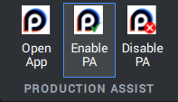
 | Open Production Assist desktop app | Opens the Production Assist desktop app. Set the mode in the app footer to Plugin in order to establish the connection to the running BricsCAD instance. See section Production Assist Synchronization. |
 | Start PA synchronization | Starts bidirectional real-time synchronization (model data, attributes, changes). Required for live calculation, snapping, and automatic updates. See section Production Assist Synchronization. |
 | Stop PA synchronization | Ends synchronization; subsequent changes are no longer transferred to Production Assist. See section Production Assist Synchronization. |
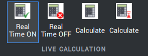
 | Enable live calculation | Enables real-time live calculations (continuous updates while you work). See section Live Calculation and Calculation Scope. |
 | Disable live calculation | Disables live calculations and reduces calculation load. See section Live Calculation and Calculation Scope. |
 | Calculate (background) | Starts an asynchronous background calculation; you can keep working while the calculation runs. See section Live Calculation and Calculation Scope. |
 | Calculate (foreground) | Runs a synchronous calculation in the foreground; the interface waits until it is finished. See section Live Calculation and Calculation Scope. |
 | Utilization (gradient) | Shows utilization values as a color gradient (finer gradation). In gradient mode, the color changes smoothly from green (low utilization) through yellow to red (high utilization). See section Display. |
 | Utilization (thresholds) | Shows utilization based on defined thresholds (for example 50/75/100%). Set thresholds in PA -> Navigation -> Load Combinations. See section Display. |
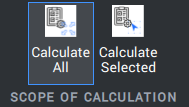
 | Calculate all | Triggers calculation for all recognized PA objects in the drawing. See section Live Calculation and Calculation Scope. |
 | Calculate selection | Calculates only the currently selected objects and is suitable for quickly checking individual systems. See section Live Calculation and Calculation Scope. |
 | Login | Opens the login dialog for Production Assist; required for cloud-based functions and licenses. |
 | PA Save | Saves PA data additionally in .LRWX format next to the DWG. Useful for support exports and for preserving PA settings. |
 | Insert point load | Inserts a point load. Detection is done primarily through the attribute Weight or through a mapping in the Property Map; layer: PA-Point Force. See section Inserting a point load. |
 | Insert line load | Distributes a load along a path (2 points) by entering name and weight; layer: PA-Line Load. Assignment in PA -> Settings -> StructuralLines. See section Inserting a line load. |
 | Insert wind load | Defines a wind area (minimum 3 points, Enter closes the polygon); layer: PA-Wind Load. Assignment in PA -> Settings -> StructuralLines. See section Inserting a wind area. |
 | Insert area load | Distributes a load across an area (>=3 points); layer: PA-Area Load. Assignment in PA -> Settings -> StructuralLines. See section Inserting an area load. |
 | Insert point force | Inserts a point force with separate components in X/Y/Z; layer: PA-Point Force. See section Inserting a point force. |
 | Select system | Selects all connected components of a system (quick test for connections). Drops and motors may be excluded. |
 | Stack trusses | Stacks trusses along a reference truss line. Requires active synchronization. |
 | Insert drop | Inserts a vertical drop element between two structures (a shared intersection point is required); related force lines on 902-SCAD_SUPPORT. See section Insert Drop. |
 | Insert rope | Connects two structures with a rope; related force lines on 902-SCAD_SUPPORT. See section Insert Rope. |
 | Trim lines | Splits and trims lines so that they meet the requirements for structural lines (no intersections except at start/end). |
This section describes how to insert blocks from the Production Assist Library into BricsCAD.
When you insert a block from the library for the first time, you must define insertion point, scale, and rotation.
Tip: The default values are scale = 1 and rotation = 0. Click the insertion point and press Enter three times to insert the block with the default values.
For practical work, it is usually more efficient to duplicate blocks that have already been inserted instead of inserting them from the library again every time. This avoids having to enter the scale again, and you can continue using the block directly with the snapping functions. Further notes can be found in the section Snapping.
Shift key and click the object once more.
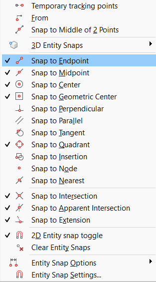
Tip: With F3, you can enable or disable object snap (ESNAP). The ESNAP settings can be found in the footer under ESNAP.
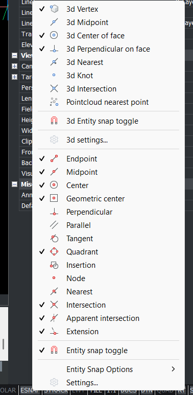
Use Shift + right-click in the drawing window to open additional snapping tools.
Note: The plug-in must be loaded for this function; synchronization does not need to be active.
Truss Snap shows green handles at the magnet points on 900-SCAD_MAGNETS. If you drag a block by one of these handles onto another one, Production Assist automatically adjusts position and rotation to fit.
Hold Shift while dragging to create a copy directly. Repeatedly pressing Ctrl switches between possible alignments.
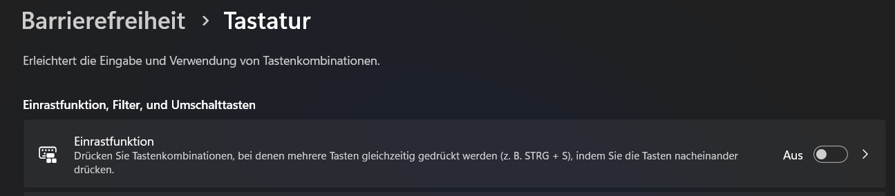
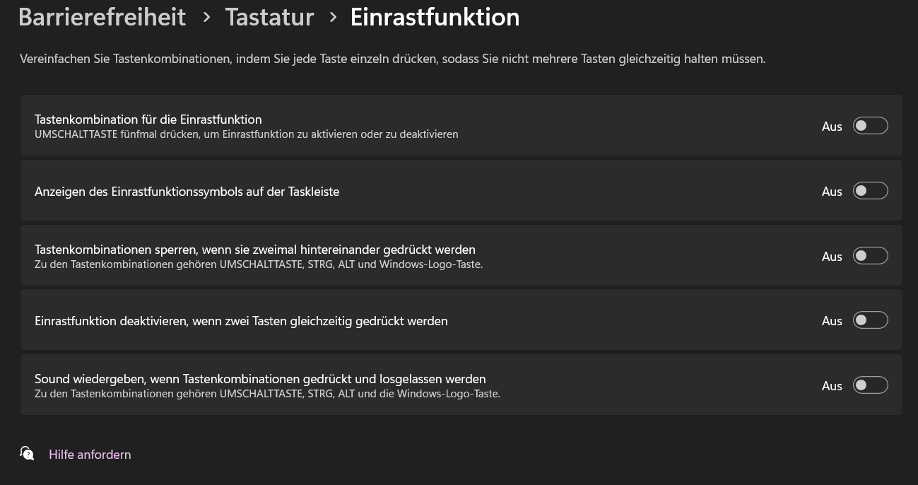
Under Windows, pressing Shift five times can open the Sticky Keys dialog; disable it in Windows settings if necessary.
The following layers are used for snapping information.
| Layer Name | Description |
|---|---|
| 003-TRUSS_SNAP | Bounding box: contour of the block (centered over the chord tube) |
| 900-SCAD_MAGNETS | Positions of the magnets / connection points |
Move (MO) moves objects only by an offset. The command does not snap automatically and also does not align the object to other components.
For trusses and similar elements, the green handles are therefore often faster: if you drag one handle, Production Assist aligns the block correctly to compatible elements. If you hold the Shift key, a copy is created directly.
For duplication, you can use COPY (CO) or the handle logic. The handle variant is usually faster because the copy can snap directly to compatible elements and align itself correctly.
If the Production Assist plug-in has been loaded via APPLOAD, you control the connection with the buttons in the Production Assist tab.
The Live Calculation function updates calculation results automatically when the model changes.
Disable Live Calculation for large models and use Calculate (background) or Calculate all instead. If results are missing or outdated, run a manual calculation or use the refresh icon in the app footer.
With Calculation Scope, you define which parts of the model are included in a recalculation. Typical options are:
Note: The selected Calculation Scope is also transferred to the desktop app. If the app and BricsCAD are connected, the objects selected for calculation are highlighted there so that you can visually check the scope.
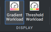
With the Display group, you control how utilizations are shown in BricsCAD.
You define which limits apply in threshold mode in Production Assist under Navigation -> Load Combinations.
In the Connections tab, you create connection objects such as drops and ropes between existing components. For this purpose, the tools create generated support blocks on 902-SCAD_SUPPORT, which are synchronized with the desktop app when synchronization is active and are included in the calculation.
Use Insert Drop to insert a vertical connection between two existing components. The tool automatically creates:
902-SCAD_SUPPORT that represents the drop.Procedure in brief:
902-SCAD_SUPPORT is visible.911-TRUSS_CENTER_STATIC; the drop is inserted between them.Edit Attributes -> Weight / Capacity.Note: When PA synchronization is active, the generated connection is synchronized with the desktop app; Weight and Capacity appear there under OIP -> Structural / Weight or OIP -> Support / Capacity.
When to use a drop:
Check after insertion:
| Layer Name | Description |
|---|---|
| 902-SCAD_SUPPORT | Storage location for drops and ropes |
| 911-TRUSS_CENTER_STATIC | Center line of the blocks; reference for intersection/connection |
Use Insert Rope to create a free, non-vertical tensile connection between two points or components. The tool automatically creates:
902-SCAD_SUPPORT that represents the rope.Short steps:
Edit Attributes -> Weight / Capacity.Special features and use cases:
Rope is not an external load, but a tensile connection that does not have to be vertical.Check after insertion:
If a rope does not work as expected, check the start/end points, system recognition, and possible competing supports.
| Layer Name | Description |
|---|---|
| 902-SCAD_SUPPORT | Storage location for drops and ropes |
| 911-TRUSS_CENTER_STATIC | Center line of the blocks; reference for connection checking |
Actions and forces are external loads on the structure. In short, the following types can be created in BricsCAD and calculated in Production Assist:
This simplified overview explains how the load types differ technically. The following sections describe insertion and the properties that must be checked in detail, such as layers, Weight, and system assignment.
Use Insert Point Load to insert a single vertical weight load at a point. The load acts downward and is suitable for individual suspended or placed weights such as loudspeakers, motors, or built-in components.
Short steps:
Weight attribute, unit: kg) and confirm with Enter.Edit Attributes whether the Weight attribute is set correctly.Important notes:
Weight attribute or through a corresponding mapping in the Property Map or Symbol Map.0,0,0 of the block definition.Use Insert Line Load to insert a load along a line. The specified total weight is automatically distributed across the defined section between start and end point.
Short steps:
Important notes:
Check after insertion:
Use Insert Wind Plane to define a polygonal area that is later used for wind calculations. The actual wind load is only created through wind direction, speed, dynamic pressure, and the selected calculation model in the desktop app.
Short steps:
Enter once the desired polygon shape has been fully defined.Important notes:
Wind Load, especially through settings such as Use structure as wind load plane.Check after insertion:
Attention: The wind area is shown only by an outline both in BricsCAD and in the desktop app.
Use Insert Area Load to define a polygon on which a uniformly distributed area load acts. This load is suitable for walkable areas, platforms, or other additional loads distributed over a surface.
Short steps:
Enter once the desired polygon shape has been fully defined.Important notes:
Use an area load when an action is not to be modeled as a point or line load, but distributed over one continuous surface.
Unlike a line load, the action is not distributed along a path, but across the entire defined area.
Typical applications include walkable areas, platform loads, evenly distributed structures, or other additional loads acting across an area.Check after insertion:
Check whether the size, position, and shape of the area match the actually loaded region.
After the calculation, verify that the area load has been assigned to the correct system.
Attention: The area load is shown only by an outline both in BricsCAD and in the desktop app.
Use Insert Point Force to insert a directed force at a point. Unlike a point load, you enter the force directly through the X, Y, and Z components so that the action can be defined freely within the coordinate system.
Short steps:
Important notes:
Check after insertion:
In Production Assist, truss connections are normally detected and created automatically as truss crosses if suitable structural elements lie correctly on top of each other geometrically. In terms of model logic, a truss cross is not a freely placed external load, but a connection or support situation between two structural elements.
Stack Truss, the 2-click tool:
Short steps (Stack Truss):
Note on tolerance and manual alternative:
For practical modeling, the following applies:
For Production Assist to recognize a truss connection correctly, the connected trusses must also lie exactly on top of each other in 3D. A position that only appears correct in plan view is not sufficient.
Whether truss crosses are created automatically is controlled in the settings via the option Automatically generate truss crosses. If this option is disabled, such connections are not created from geometry alone.
With the setting Allow truss crosses within the same object, you additionally control whether such connections are also permitted within the same object.
If a connection is created unexpectedly or does not appear, first check the geometry, elevation, and whether the affected object is allowed to be used as a receiving element at all.
For engineering interpretation, the following applies:
Truss Cross Type.Flexible, Compression only, Tension only, and Rigid. This defines whether the connection is freely rotatable, transfers only compressive forces, only tensile forces, or transfers forces and moments without relative movement.For practical checking, the following applies:
Especially relevant for documentation and approval are:
Truss Cross TypeThis section describes how to check synchronization, calculation, and display in a targeted way on the current model.
For a quick plausibility check, the following procedure is recommended:
Live Calculation or a manual calculation is active.Calculation Scope to match the purpose of the check, usually ALL for an overall check.Vz, support reactions, and error messages together.Pay particular attention to:- correct adoption of geometry, loads, and attributes into the selected Calculation Scope
For documentation and verification, note down:
the verification assumptions used, for example Live Calculation and Calculation Scope
the applied load or model change
the checked result values, for example Combined Deflection Du, Vz, or support reactions
the technical interpretation of noticeable results
For free-standing systems, ground-support elements from the library are used. The design principles correspond to those of normal truss systems, supplemented by specific parameters such as wind loads, friction coefficients, and floor bearing capacity.
Example workflow: inserting Ground Support
Special feature: These Ground Support blocks also contain an additional single point on the layer 910-LAYHER_Support. This point transfers the position of the floor support to Production Assist. Layer assignment is done in the desktop app under Settings -> StructuralLines -> LoadLayers.
Note: The settings for Ground Support Attachments as well as the calculation of ballast and floor load are configured in the Production Assist desktop app.
Important aspects of Ground Support:
ProductionAssist_FloorLoad and ProductionAssist_FloorLoad_Text. Activate both layers if you want to check distribution and peak values.For practical checking, the following applies:
The following overview helps to distinguish between what Production Assist provides and what must be checked externally:
| Question | What does Production Assist show? | What must be checked or defined externally? |
|---|---|---|
| Where are loads transferred into the ground or the ceiling? | Support positions, support reactions, and result layers such as ProductionAssist_FloorLoad and ProductionAssist_FloorLoad_Text | Whether the real bearing area, load distribution, and load transfer may actually be assumed the same on site |
| How large is the governing ground pressure? | Reaction forces and the floor loads derived from them in the model | Permitted ground pressure, load-bearing capacity of ceilings, coverings, substructures, or load-distribution measures |
| Is the available ballast and assumed friction sufficient? | Effects of the applied geometry, load combinations, and friction values on stability and support reactions | Whether the assumed friction coefficients, ballast masses, and their actual arrangement on site are reliable and approved |
| Are basement ceilings, underground garages, or traffic surfaces sufficiently load-bearing? | Additional loading from the modeled system at the respective support points | Permitted imposed loads, traffic loads, and area loads of the structure based on as-built documents, operator approvals, or structural review |
| Which documents are needed for approval or verification? | Plan view, structural model, load images, and result layers from the calculation | Formal verifications, approvals, code assumptions, safety concepts, and project-specific boundary conditions |
If load-distribution measures are used, document their position, dimensions, material, and assignment to the respective support points. Also record whether these measures have already been considered in the model or are only included in the external check.
Frequently asked questions about Ground Support and floor loads:
Dead weight and additional ballast should be documented separately:
Wall fixings and horizontal supports should not be modeled as point, line, or area forces if they actually hold, guide, or brace the structure. Loads describe actions on the system. A Wall Support, by contrast, describes a reaction possibility of the system and therefore belongs statically to the support conditions.
In the current modeling logic of this documentation, Wall Support is generally not described as a separate dedicated support type, but as a point support with specifically defined reaction directions. In practice this means:
For practice, this means:
| Case | Recommended model |
|---|---|
| Wall applies only an external action | Through point, line, or area forces |
| Wall holds the system laterally or prevents displacement | Through a support point with suitable reaction direction |
| Wall anchorage also carries vertical forces | Model it as a load-bearing support only if this corresponds to the real construction |
| Several wall connections along one system | Several discrete support points instead of one generalized substitute load |
After every calculation, check especially for Wall Supports:
If you are unsure whether a wall element should be modeled as a support or as a load, the following simple question helps: if the wall absorbs a reaction force from the structure, it is a support. If the wall acts only as a predefined load on the structure, it is a load.
Motors and chain hoists are inserted via the CMF block. In the Production Assist model logic, hoists are not external loads, but suspension points or supports through which the structure transfers loads into the suspension. Before insertion, make sure object snap (ESNAP) is active and the required layers are visible.
CMF block from the library.Edit Attributes dialog, enter values for Hook Height, Hoist ID, and Weight (dead weight of the chain hoist itself, unit: kg).OIP -> Support (unit: kg).911-TRUSS_CENTER_STATIC) as a reference so that snapping detects a valid connection.LOAD.Note: In BricsCAD, the chain of the CMF hoist component is not shown graphically.
For engineering interpretation, the following applies:
Weight describes the dead weight of the hoist component itself. The actual hook force results only from the connected structural model, the attached loads, and the calculation.Hook Height, position, and connection to the structure must match the real geometry. Otherwise, implausible hook forces, incorrect connections, or wrong load paths may result.Hoist ID values are especially important so that assignment, verification, and reporting remain consistent.For practical checking, the following applies:
LOAD with the permitted capacity of the real chain hoist and the associated slinging or suspension situation.Particularly relevant for documentation and approval are:
Hoist IDOIP -> SupportLOADIf a hoist shows implausibly high or unusually low forces in the calculation, first check geometry, connection to the structure, multiple support conditions, and load distribution before assessing the hoist capacity itself.
Orientation of the chain hoist and its effect on the calculation
By default, chain hoists in Production Assist are modeled with the motor at the bottom, meaning climbing mode. In the object properties (OIP), you can switch the motor orientation, for example motor up / motor down. In addition, the OIP settings contain an option that allows the motor weight to be excluded from the structural calculation. If this option is activated, the motor's block attribute Weight is ignored in the load calculation.
Attention: This does not change the graphical representation of the chain-hoist block in the drawing. The setting affects only the calculation logic.
| Layer Name | Description |
|---|---|
| 911-TRUSS_CENTER_STATIC | Center line of the blocks; reference for connection checking |
In practice, structures are often not supported by just one support type, but by a combination of floor supports, suspension points, and, if necessary, lateral bracing. For Production Assist, it is crucial that every support point has a clear structural function in the model and that the same degree of freedom is not accidentally supported more than once.
Important: Point, line, and area forces describe actions on the structure. They do not replace a support. If a wall, a floor, or a suspension point actually holds or guides the structure, that effect should be modeled as a support and not only as an external load.
| Combination | Typical use | Limitations | Relevant aspects for model and checking |
|---|---|---|---|
| Ground Support + Hoists | Free-standing or partially suspended systems in which part of the load is transferred to the floor and part via suspension points | Load distribution does not result automatically from intention, but from geometry, stiffness, and support definition. An unrealistic combination can lead to wrong support reactions. | Ground-support points must be modeled cleanly as floor supports; hoists need a valid connection to the structure. After the calculation, check in particular ProductionAssist_FloorLoad, hook forces in the Load attribute, and the support display in the structural model. |
| Ground Support + Wall Support | Systems with floor support and additional lateral guidance or load transfer through wall connections | The critical issue is distinguishing between a load-bearing wall support and mere horizontal bracing. If wall connections are modeled too stiffly or in the wrong directions, the system can become overdetermined. | Wall supports should only restrain the degrees of freedom that actually exist. Check whether the floor supports carry the main vertical load and the wall supports provide only the intended horizontal or local reactions. |
| Hoists + Wall Support | Suspended systems with additional lateral guidance, back anchorage, or horizontal stabilization | Wall supports must not unintentionally replace suspension points. An overly rigid wall support can distort the load distribution between hoists and wall connections. | Use hoists for the vertical load-bearing action and wall supports only where horizontal or specifically defined additional reactions are actually absorbed. Check reactions, deformations, and possible error layers after every model change. |
| Ground Support + Wall Support + Hoists | Complex hybrid systems with floor supports, suspension points, and lateral anchorage | This is the most error-prone combination because several support types can influence the same deformations and reaction paths simultaneously. Small modeling mistakes have particularly strong effects here. | Model every support point with a clear function: carrying, guiding, or stabilizing. Check the recognized structural model, support positions, result layers for deformation and utilization, and, if necessary, ProductionAssist_Error or support-related error messages. |
| Multiple Hoists combined with Ground Support or Wall Support | Trusses or frames with multiple suspension points and additional auxiliary supports | Multiple supports of the same or similar function increase the risk of unclear load paths. Without clean geometry and correct assignment, individual supports can receive too much or too little load. | Clear IDs, correct center lines, and understandable support positions are especially important here. Check whether the system is recognized as one connected system as expected and whether peak values at individual hoists or supports are plausible. |
For practical modeling, the following applies:
The basic settings of the Production Assist Library are managed in the Settings section. This section shows which building blocks make up the library for BricsCAD and where this information is maintained.
For practical work, the important point is that not all information is stored in the same place. Part of it is contained directly in the DWG blocks, part in the layers used, and another part is added through mappings in Production Assist.
| Type | Description | Typical storage location or management |
|---|---|---|
| DWG blocks | The actual BricsCAD symbols and block definitions for trusses, motors, loads, or other components. They contain geometry, attributes, and, if necessary, prepared internal helper elements. | In the Production Assist Library and, after insertion, as block definitions in the DWG file |
| Line structure | Lines, points, or other helper geometry inside a block, with which Production Assist recognizes structure, loads, supports, or connections. | Inside the block definitions on the corresponding layers |
| Cross-section information | Information about which structural behavior a structural element should have in the calculation, for example the used cross-section or internal structural definition. | Through prepared Structure elements in the block or through the layer definitions in the Structure by Line area |
| Assignments | Mappings with which blocks, attributes, and external content are assigned to the corresponding Production Assist functions. This includes in particular the Symbol Map and Property Map. | In the Resource Manager or in the corresponding assignment tables of Production Assist |
The following sections distinguish between three levels:
If you want to build your own content or adapt existing blocks, you can find the further details in the sections Preparing your own BricsCAD library for Production Assist, Structure by Line, Symbol Map, and Filling attributes in BricsCAD.
Using Load Layers, you define which geometries on a layer are interpreted as loads. The decisive factor is not only the layer name, but above all the load type activated in the settings.
| Type | Typical geometry | Typical storage location | Relevant layer logic | Description |
|---|---|---|---|---|
| Point load | Point or point object | As an object in the drawing or inside prepared blocks | Often recognized through the Weight attribute, the Symbol Map, or a suitable load assignment | Concentrated gravity load at a single point of application |
| Line load | Line | As a line in the drawing or as recognized line geometry in a block | If no special other load type is activated, lines on a load layer are interpreted by default as line loads | Distributed load along a linear section |
| Area load | Closed polygon or area | As a drawn area or polygon in the drawing | Via Use as Area Load in the Structural Lines area | Distributed load across one continuous area |
| Point force | Point or point object | As a point object in the drawing or in a suitable block | Via Use as Point Force in the Structural Lines area | Directed force with X, Y, and Z components |
| Free line load | Line | As a freely positioned line in the drawing | Via Use as Free Line Load in the Structural Lines area | Line load that does not have to lie completely on a structural element |
| Wind area | Closed polygon or area | As a polygon in the drawing or as a correspondingly defined area | Via Use as Wind Load in the Structural Lines area | Wind-relevant area with its own wind-load logic |
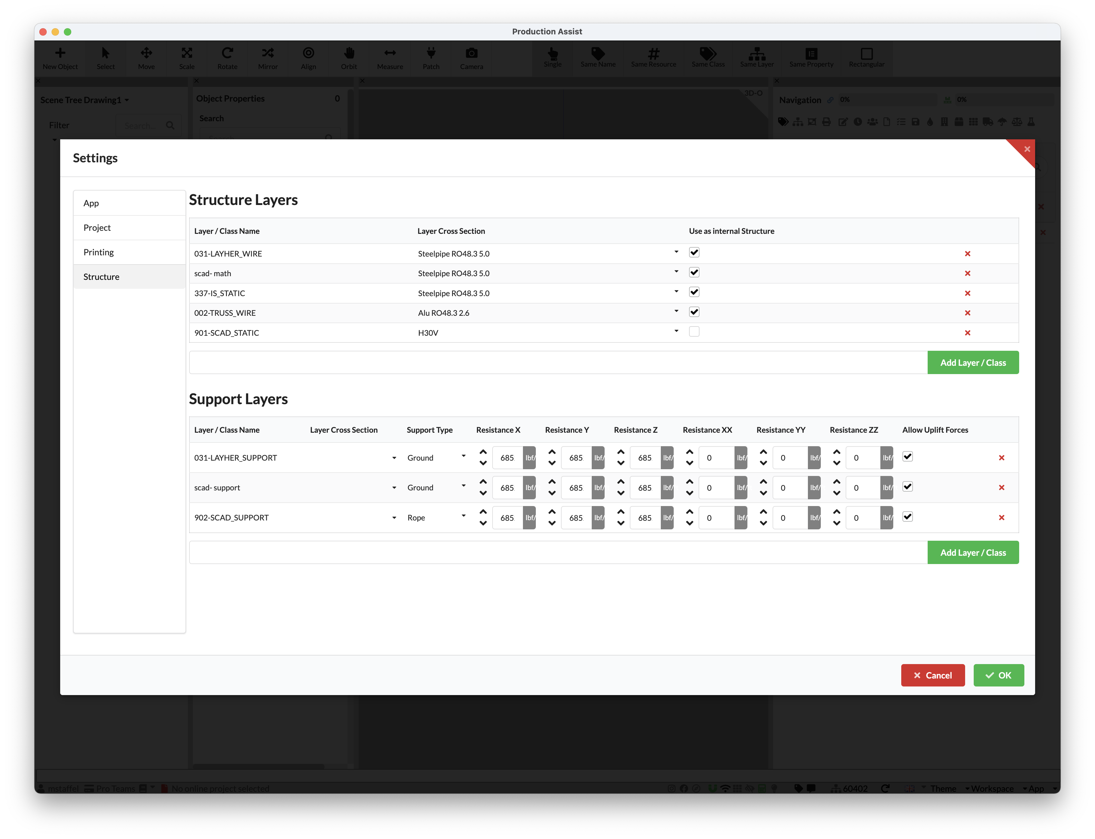
Using Support Layers, you define which geometries are evaluated as supports or support elements. The distinction is important: not every support type is defined exclusively through these settings. Some elements are inserted as prepared blocks and already carry their own logic.
| Type | Typical geometry | Typical storage location | Relevant support logic | Description |
|---|---|---|---|---|
| Suspension point | Block or symbol | Usually as an inserted block, for example hoist component | Support data through block, attributes, and OIP, not primarily through a pure support layer | Support that transfers loads into a higher-level supporting structure |
| Ground Support | Point or special attachment | Point object on a support layer or prepared Ground Support block | Support Type = Ground Support Attachment | Floor or anchor support for free-standing or braced systems |
| Rope | Line or sequence of points | Line or points on a support layer, additionally also as an inserted rope element | Support Type = Rope, optionally Use as Line Support | Tension-loaded rope or line-based support element |
| Drop | Block or line-based support element | Typically as an inserted drop element on a support-related layer | Usually through prepared geometry and connection recognition, not only through a generic layer assignment | Vertical connection with support effect between two structures |
| Wall Support | Point support or support block | Depending on workflow as a defined support point or prepared support element | In this documentation usually modeled as a support with specifically directed reactions | Lateral or local support at a wall or existing structure |
| Floor | Floor reference or floor support | Depending on workflow via Ground Support, floor assignment, or project-specific modeling | Often not represented as a separate dedicated layer type, but via Ground Support or floor assignment | Reference to support against the floor or load transfer into the subsoil |
Using Structure Layers, you define which lines, edges, or other geometries are read as load-bearing structural elements in the calculation. This is the basis for Production Assist to recognize trusses, tubes, lattice members, or other structural members as a static system at all.
| Field or aspect | Meaning |
|---|---|
| Layer / Class Name | Name of the CAD layer or class on which the geometries to be interpreted as structure are located |
| Layer Cross Section | Cross-section that is assigned by default to structural elements on this layer |
| Layer Color Map / Color Override | Option to override cross-sections through color or a defined color assignment |
| Use from Geometry | If activated, the cross-section is taken directly from the geometry or the object itself |
| Use as internal Structure | Marks elements as internal structure that can be treated differently in display or calculation logic |
For practical work, the following applies:

Settings.Note: Disabling synchronization does not delete data that has already been synchronized in the desktop app. It only interrupts the live connection.
With a custom library, you prepare your own BricsCAD blocks so that Production Assist can reliably read structure, loads, supports, and further properties from them. There are two basic approaches for this preparation:
Both approaches are possible, but they pursue different goals.
| Approach | Typical use | Advantage | Limitation |
|---|---|---|---|
| Symbol Map | Existing blocks should be quickly linked to a suitable symbol from the Production Assist Library. | The existing block can continue to be used without rebuilding it. This is often the fastest path to a first working workflow. | The assignment works meaningfully only if there is a technically suitable symbol in the Production Assist Library and the alignment of the block matches it. |
| Layer integration | Custom blocks should bring their structural logic directly through lines, points, or areas within the block definition. | Very flexible, because you can define structure, loads, supports, and helper geometry independently of existing symbols. | The block must first be prepared cleanly so that layers, geometry, and cross-sections are recognized correctly. |
For a practical decision, the following applies:
The following sections show the individual components of this preparation in detail, especially Structure by Line, Symbol Map, and Filling attributes in BricsCAD.
With the function Structure by Line, you define load-bearing geometry directly through lines, curves, and points in BricsCAD. This method is especially flexible when custom blocks should not only be displayed graphically, but also be prepared for structural evaluation.
Production Assist does not recognize these geometries solely by their shape, but through the assigned Structure Layers and Support Layers. The names of these layers or classes can be chosen freely. Assignment is done in the settings under File -> Settings in the Structural Lines area.
For the structure definition, lines and curves describe the load-bearing elements. Production Assist later uses this geometry to identify the load path, the connection between components, and the basis for the calculation.
| Field | Description |
|---|---|
| Layer / Class Name | Name of the layer or class on which lines and curves are read as load-bearing structure. |
| Layer Cross Section | Standard cross-section assigned to all structural elements on this layer. |
| Layer Color Map / Color Override | Allows the cross-section to be overridden through layer color or a defined color assignment. |
| Use from Geometry | Takes the cross-section directly from the object geometry if this information is available. |
| Use as internal Structure | Marks elements as internal structure. This is useful, for example, when helper or internal geometry should be displayed differently or handled separately. |
To create a new entry, enter a new layer or class below the table and confirm with Add Layer / Class.
Note: In principle, all suitable line and curve geometries in BricsCAD can be prepared as structural members in this way.
For Production Assist to recognize the geometry correctly as one connected structure, the lines must follow certain rules:
| OK | Description | Not OK |
|---|---|---|
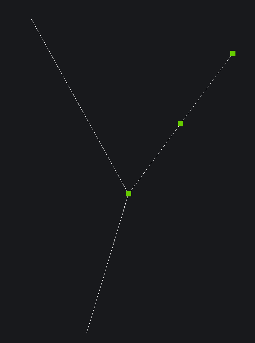 | Endpoints must lie exactly on other lines or on the endpoints of connected lines. Only then does Production Assist recognize a reliable connection between the structural members. | 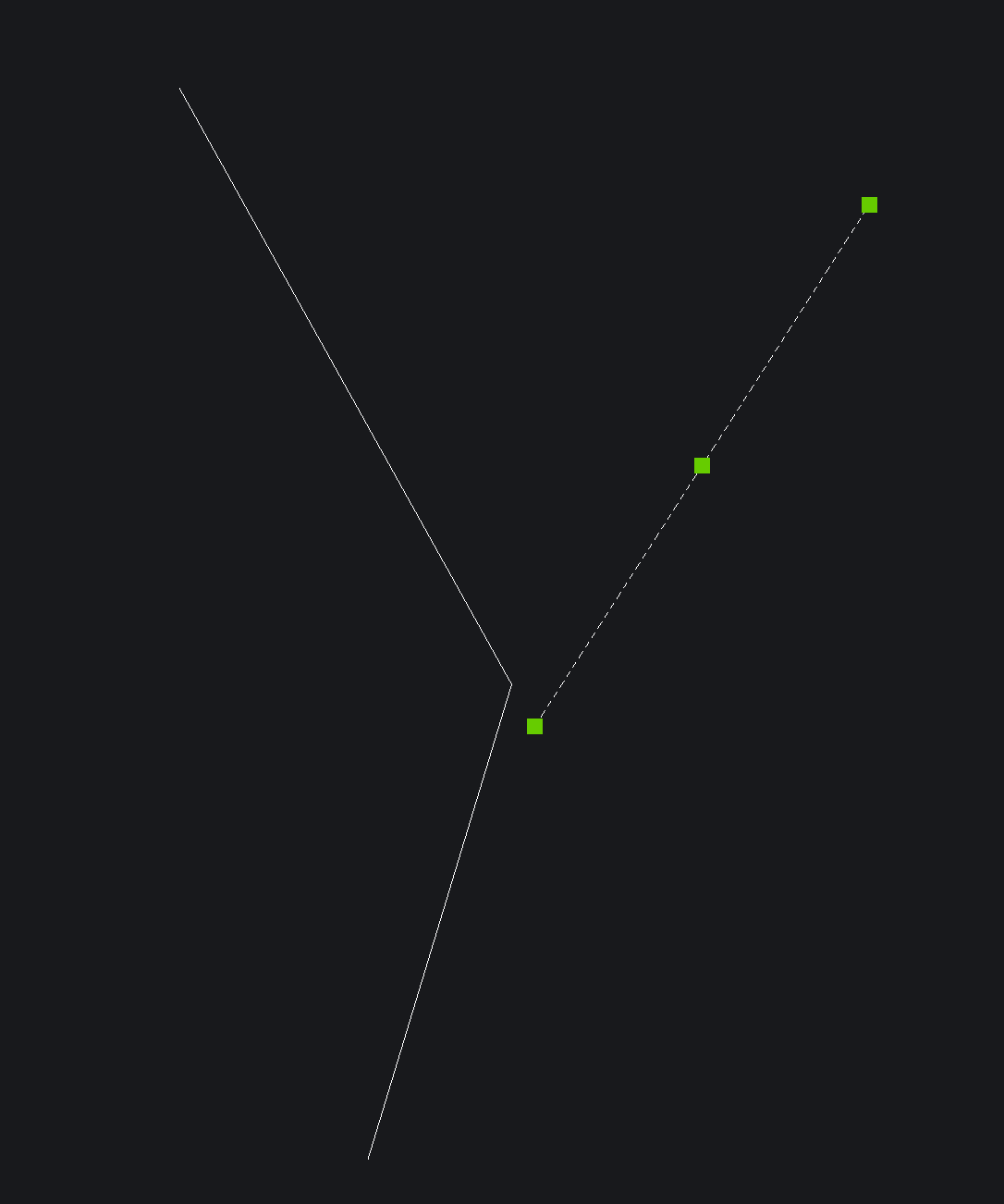 |
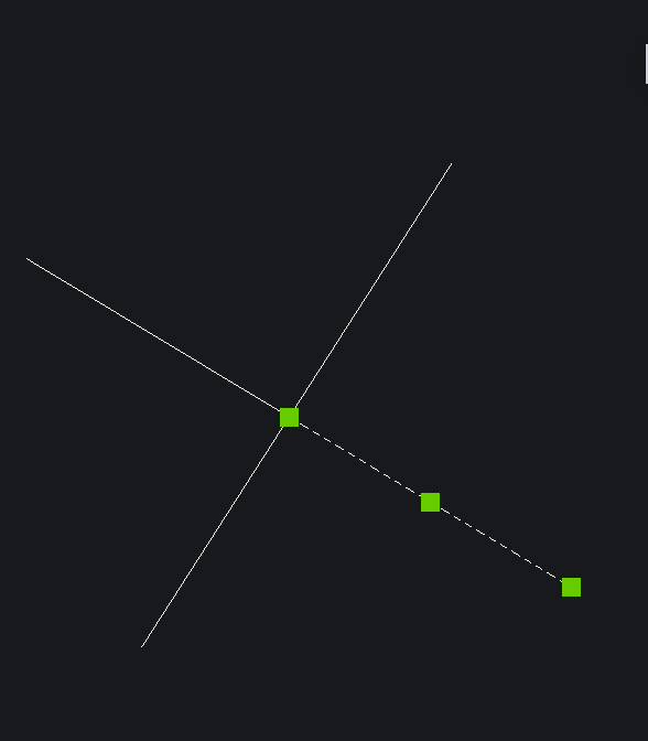 | Crossing lines are not automatically connected through intersection alone. For a real connection, at least one line must end with its endpoint on the other line. | 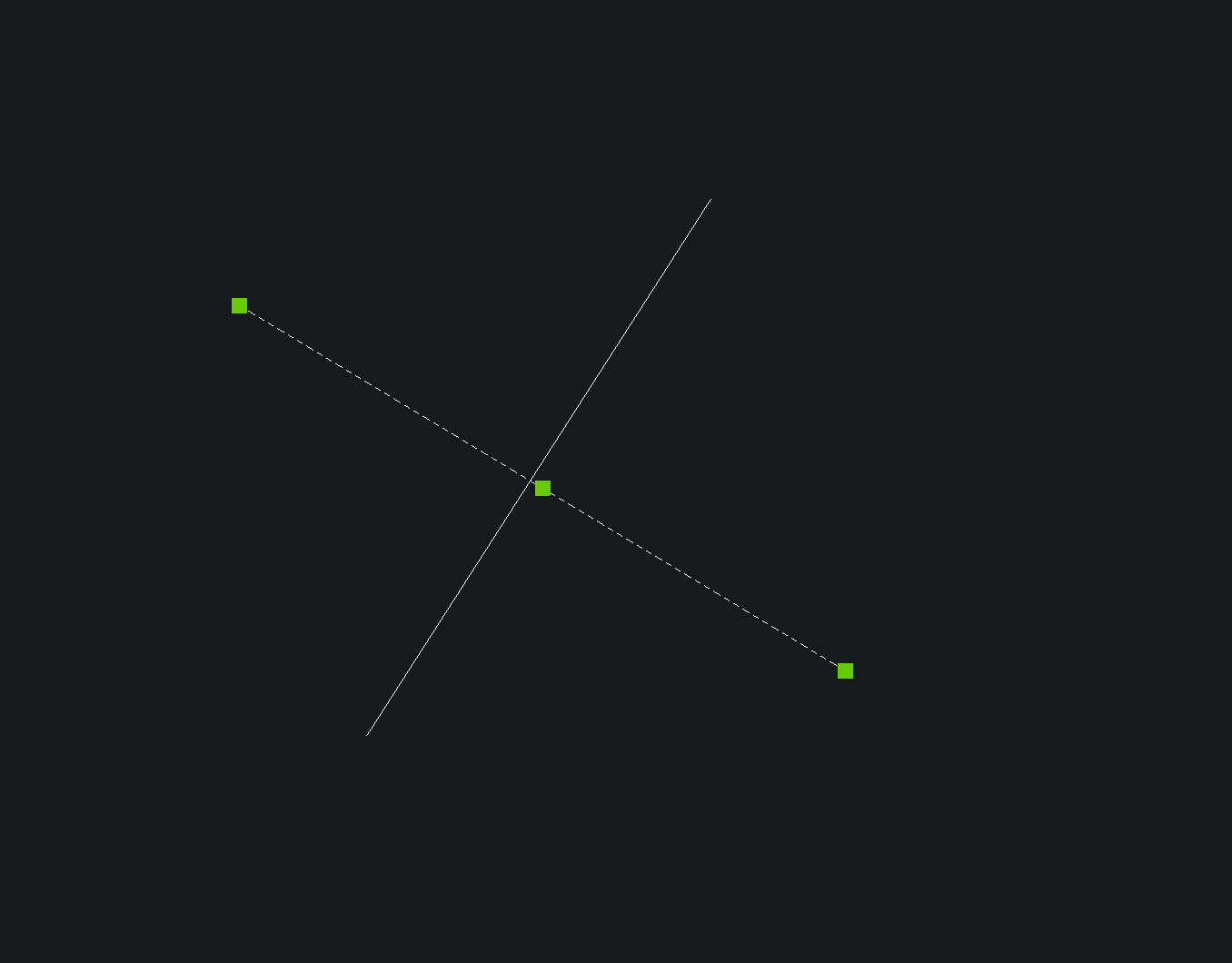 |
For practical work, the following applies:
Supports can also be defined in this way. Depending on the support type, points or lines on previously defined Support Layers are used. These settings are located in the same dialog area under Support Layers.
| Field | Description |
|---|---|
| Layer / Class Name | Defines the name of the level in BricsCAD on which all points are read as supports. |
| Layer Cross Section | Mainly for ropes: Defines the cross-section or rope profile used for elements on this layer. |
| Support Type | Defines whether the layer is treated as Rope or as Ground Support Attachment. |
| Use as Line Support | If activated, lines on this layer are interpreted as line-based support geometry, for example for ropes. |
| Resistance X / Y / Z | Defines the translational stiffnesses of the support in the respective axis directions. |
| Resistance XX / YY / ZZ | Defines the rotational stiffnesses of the support; these are especially relevant for Ground Supports. |
| Allow Uplift Forces | Defines whether the support may also absorb tensile or uplift forces. |
| Uplift Value | Optional limit value for permitted upward forces. |
For practical modeling, the following applies:
With the Symbol Map, you assign existing BricsCAD blocks to suitable symbols from the Production Assist Library. This is the fastest approach when existing CAD content is to be reused without rebuilding the block definition itself with helper geometry or structural layers.
To get started, open the command File -> BricsCAD Integration -> Prepare Symbol for Production Assist.
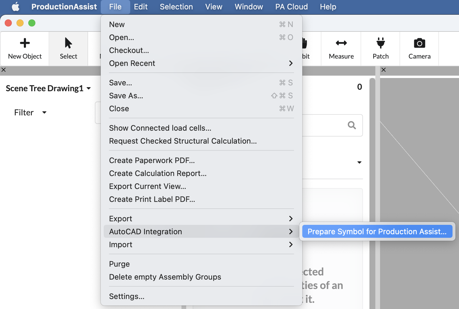
This opens a dialog listing all blocks from the current drawing. There you define which symbol from the Production Assist Library should be assigned to which CAD block.

For practical assignment, the following workflow is recommended:
Edit.The important point is not only a similar look, but above all the technical equivalence. A graphically similar block is only suitable for assignment if the selected symbol also performs the same structural or functional role in the model.
Attention: The orientation of the block and the Production Assist symbol must be the same.
The assignment is stored in the Symbol Map. This is located in the Resource Manager and can later be checked, adapted, or extended there.
For technical classification, the following applies:
For practical checking, the following applies:
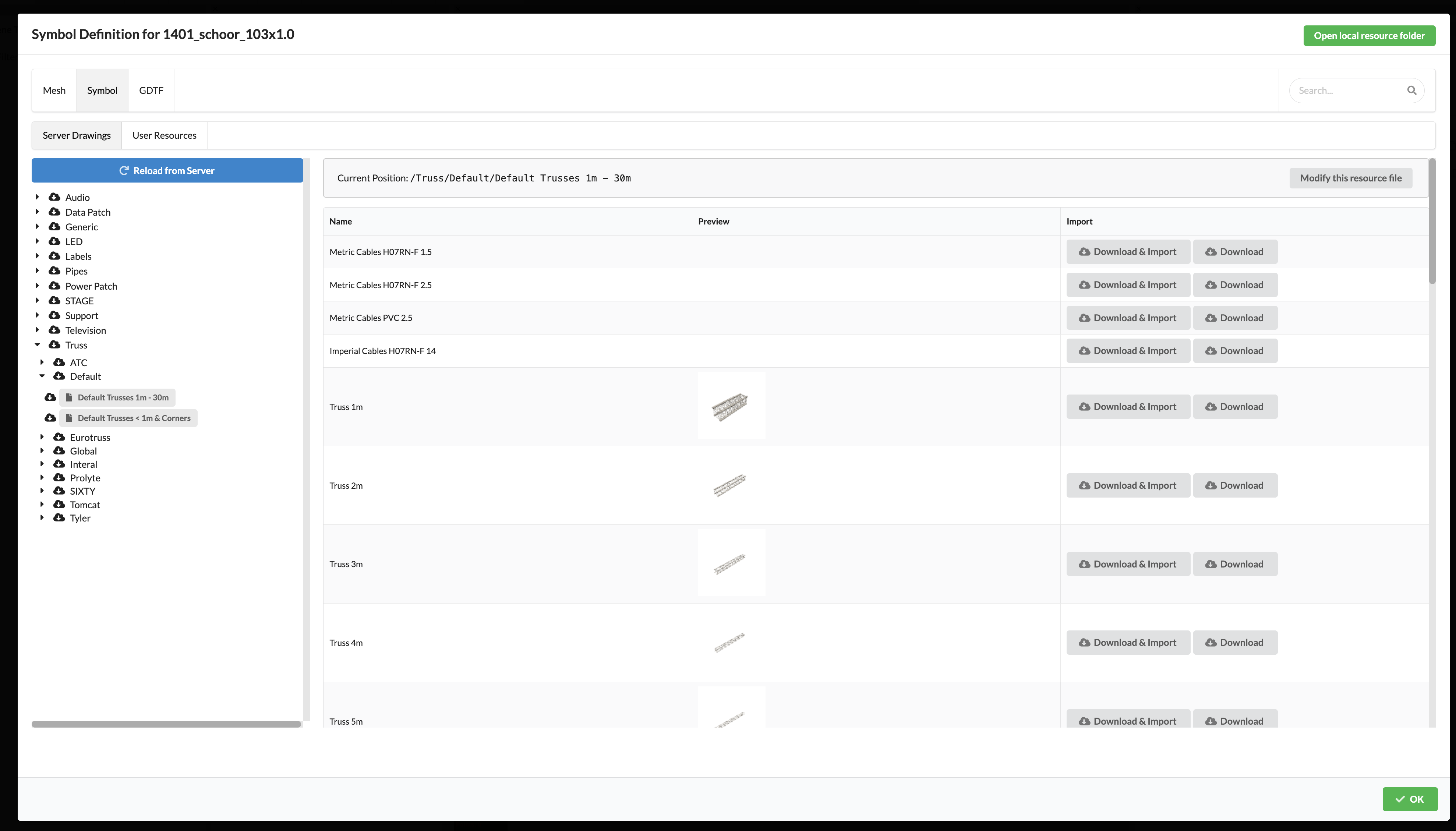
| Symbol Map | Resource Manager |
|---|---|
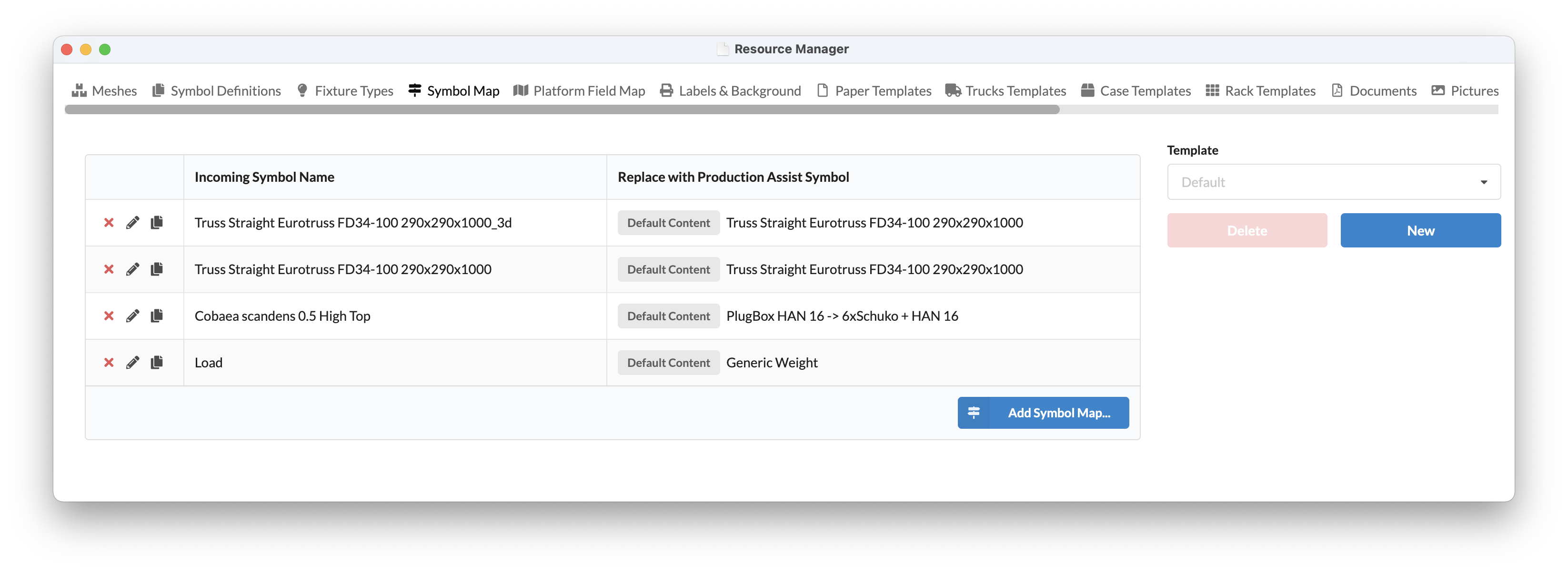 |  |
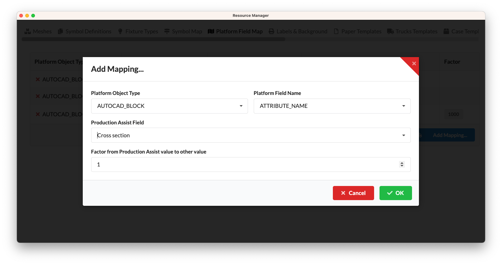
With the Property Map, you define which values are exchanged between block attributes in BricsCAD and properties in Production Assist. This allows calculated or managed values to be shown directly in block attributes and reused consistently when the drawing is reopened.
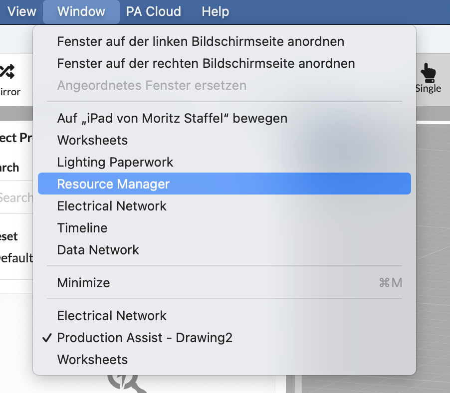
You can find the Property Map under Window -> Resource Manager.
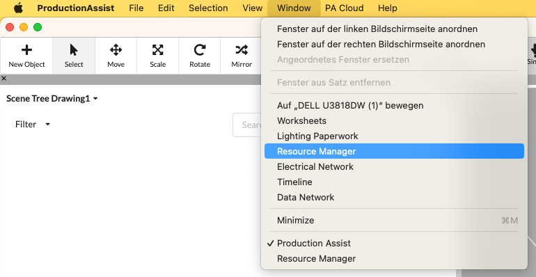
Open the Property Map tab there.
For practical work, the following workflow is recommended:
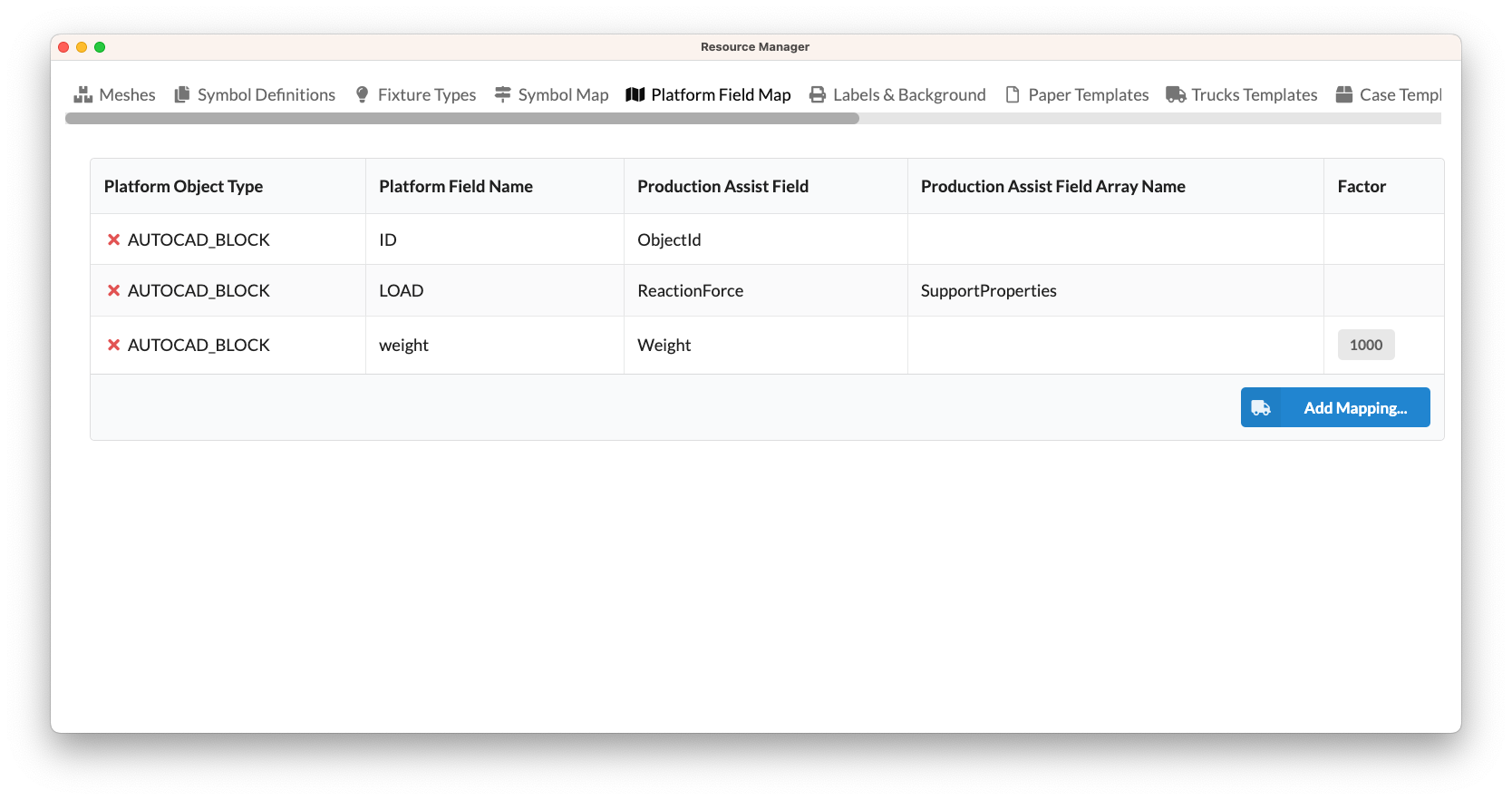
| Field | Description |
|---|---|
| Platform Object Name | Designates the platform type to which the mapping refers. In the BricsCAD or AutoCAD integration, this is typically AUTOCAD_BLOCK. |
| Property name of the platform | Name of the block attribute on the CAD side. The spelling must match exactly, including upper and lower case. |
| Production Assist Property Name | Name of the property in Production Assist that should be linked to the block attribute. |
| Production Assist Property Array Name | Used if the desired property is located inside an array property. |
| Factor | Conversion factor by which the CAD value is divided so that it matches the base unit used in Production Assist. |
Important for the technical interpretation:
Note: Production Assist uses base units. For weight this is, for example, grams, for lengths millimeters, and for forces kilonewtons. If a CAD attribute is maintained in another unit, the appropriate factor must be entered.
The following units are used as base units in Production Assist:
| Property type | Base unit in Production Assist |
|---|---|
| Weight | Gram |
| Length | Millimeter |
| Force | Kilonewton |
Example 1: The weight of an object is to be linked with an attribute in BricsCAD. In BricsCAD, the value is in kilograms, while Production Assist expects grams internally. For this, the factor
0.001is used. 1 kilogram / 0.001 = 1000 grams
Example 2: The weight of an object is to be linked with an attribute in BricsCAD. In BricsCAD, the value is in pounds, while Production Assist expects grams internally. For this, the factor
0.00220462is used. 1 pound / 0.00220462 ≈ 453.59 grams
For practical checking, the following applies:
To add your own mapping, click Add Assignment....
For checking and editing blocks in BricsCAD, some standard commands are especially helpful. The following commands are particularly useful when preparing custom blocks, checking helper geometry, or making displays easier to read during editing.
| Command | Typical use | Practical note |
|---|---|---|
BEDIT / BLOCKEDIT | Opens the block editor to check or change the content of a block definition. | Use this command if you want to adjust layers, helper lines, points, attributes, or internal structural geometry directly inside the block. |
PDMODE | Controls the display style of point objects in the drawing. | Useful if point loads, support points, or other helper points should be made more visible during editing. Typical values are, for example, 0 for point, 2 for plus, 3 for cross, 32 for circle, and 64 for square. These values can also be combined. |
BKGCOLOUR | Changes the background color of the model space. | Helpful if lines, points, or layer colors are difficult to read on the current background and you want to improve visibility for editing. |
For practical work, the following applies:
BEDIT or BLOCKEDIT when you want to understand which geometry in the block is actually evaluated by Production Assist.PDMODE if point objects exist in the drawing but are visually hard to recognize.BKGCOLOUR only if this actually makes geometry checking easier; the setting improves visibility but does not change the evaluated data.