

A Ground Support Attachment is a point support that transfers forces from a standing or braced structure to the ground or an anchor point. Without correctly assigned supports, Production Assist cannot calculate the complete structural system.
This page explains how to connect a Ground Support Attachment to a structure and check the support properties that matter for the calculation.
For help choosing the right type of support, see the FAQ on choosing Ground Support.
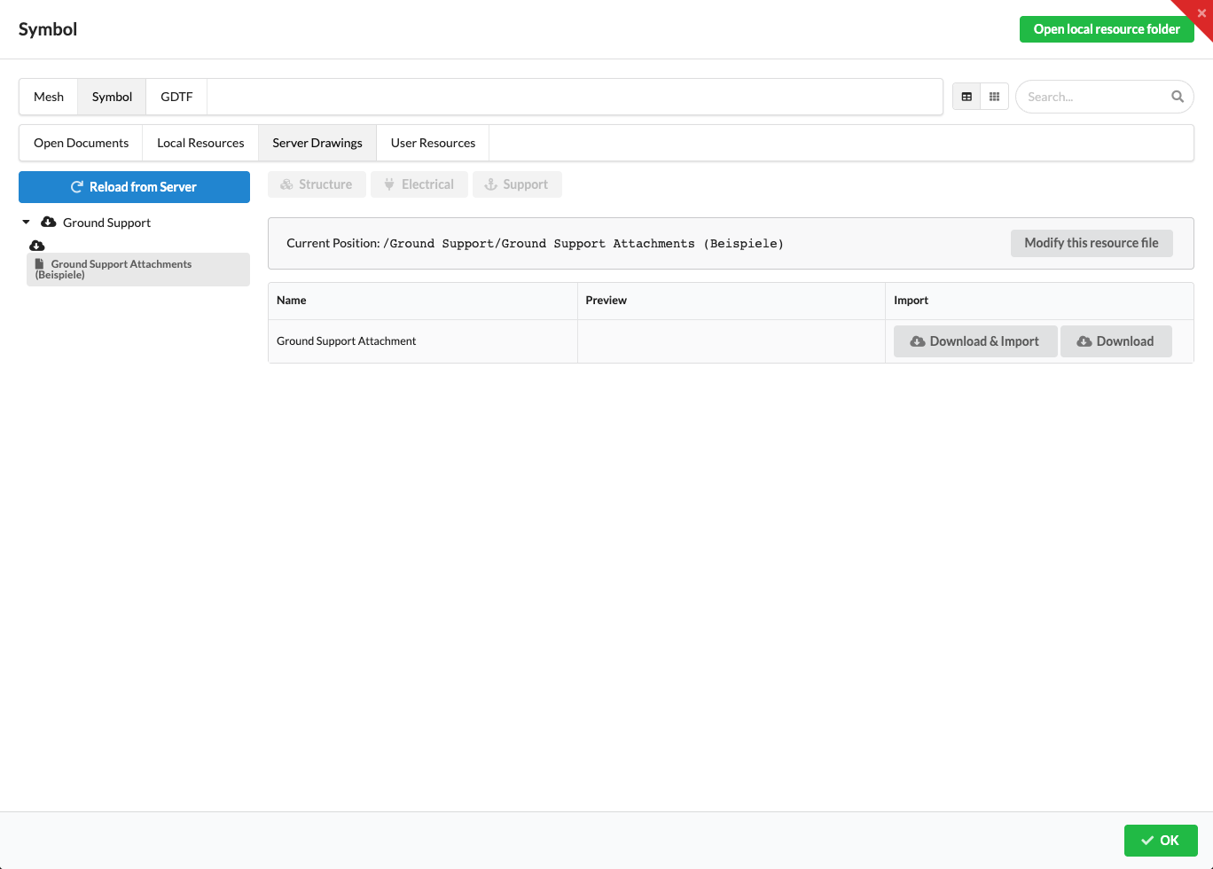
After placing the attachments, check in Object Properties that each one is assigned to the correct structural object. For the calculation, Production Assist assigns the support point to a nearby structural member. If an attachment is not on the structure, it can create a separate or incorrectly supported calculation node. If calculation errors occur, check the position and connection to the structural member.
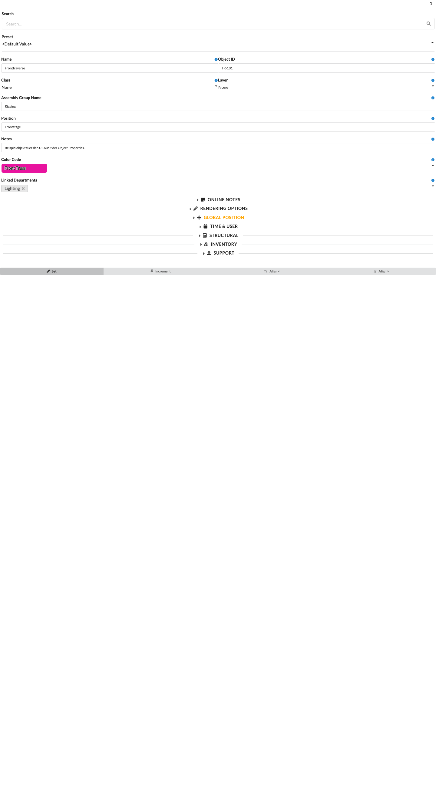
The following current example shows the general layout of Object Properties. It contains a different, synthetic example object; the fields shown are not properties of a Ground Support Attachment. The support fields displayed depend on the selected object.
In the Support Layers in Settings, assign a support type to a layer or class. The application distinguishes these types:
| Support Type | Geometry | Behavior and Use |
|---|---|---|
| Ground | Point | Ground or anchor support for standing and braced systems. Stiffnesses and verification values are set on the support object. |
| Rope | Point or line | A connection that carries tension. It does not replace a ground support that must carry compression. |
A Hoist, Drop, or House Rigging Point represents a different part of the load path. These types are not available in Support Layers. Use the appropriate object for each real load path.
Ground Support Attachments do not have separate names for “fixed,” “pinned,” or “anchored.” Their calculation behavior is determined by their stiffnesses, support orientation, and other support properties. Set the values to match the real structure and the manufacturer's specifications.
| Model Variant | Relevant Setting | Meaning |
|---|---|---|
| Translation along X, Y, or Z | Resistance Force X / Y / Z | Sets the translational support stiffness in the corresponding direction. |
| Rotation about X, Y, or Z | Resistance Moment X / Y / Z | Sets the rotational support stiffness about the corresponding axis. |
| Rotated object | Rotated Ground Support | Applies the object's rotation to the FEM support axes. Without this option, the support axes follow the global coordinate system. |
| Uplift forces | Allow Uplift Forces and, for automatically generated floor supports, the corresponding option in the active load combination | When enabled, the support can also carry upward tensile forces. For automatically generated floor supports, the setting comes from the active load combination. |
| Prescribed support displacement or settlement | Node Displacement X / Y / Z | Prescribes displacement of the support node along the three FEM axes. This does not change the object's position in the drawing. Use these values to model a known support movement or settlement; with finite stiffness, they produce corresponding support reactions. |
The table rows describe setting cases; they are not additional choices in the Support Type field. A calculation setting does not confirm the support's capacity or its actual anchoring on site.
| Setting | Effect |
|---|---|
| Resistance Force X / Y / Z | Defines translational stiffness along the three axes. |
| Resistance Moment X / Y / Z | Defines rotational stiffness about the three axes. |
| Allow Uplift Forces | When enabled, the support can also carry upward tensile forces. When disabled, the calculation model releases the support if an uplift reaction occurs. For automatically generated floor supports, the corresponding option in the active load combination controls this behavior. |
| Rotated Ground Support | Applies the object's orientation to the FEM support axes. |
| Node Displacement X / Y / Z | Specifies the prescribed displacement of the support node along the three FEM axes. These values affect the FEM model but do not move the attachment in the drawing. |
| Check Friction Results and Value Friction between Ground and Support | Enables the friction check and sets the friction coefficient used. Use a value supported by evidence for the actual material pair. |
For automatically generated floor supports, the corresponding option in the active load combination controls whether upward forces can be carried. Check the calculated support reactions and compare the setting with the real anchoring.
After insertion and whenever loads, wind, or ballast change, check:
Use Select System Objects to check whether an attachment and the structure belong to the same structural system. The Ground Support modeling and calculation check tutorial gives an example workflow for modeling and checking a braced structure.
Note: A calculated support does not replace checking the real anchoring, ballast, bearing surface, or the capacity of the ground or ceiling.