

Open File > Settings... to access the central dialog for app, project, printing, and integration options in Production Assist.
The current dialog screenshots show example data from a new drawing. Long settings sections are shown as visible dialog excerpts; scroll to reach additional fields.
The MCP section displays connection details for the MCP server of the running desktop app. This section is not available in the browser. The server icon in the Information Line also opens the MCP connection details.
The HTTP Connection section displays the port in use, a local connection address, and, when available, IPv4 addresses for connections from the local network. Each address ends in /mcp. Use the local address for an MCP client on the same computer and a network address for a client on another device. Select the copy icon next to an address to copy it to the clipboard.
Under Local STDIO Targets, you can find registered Production Assist instances from the desktop app and supported CAD plugins. Each entry shows the host application, channel, version, installation ID, and status. Select a ready target. The associated application must remain open while the MCP client is connected.
In the dialog for adding a custom MCP connection, select STDIO as the type. Transfer the values from Manual STDIO Configuration to the corresponding fields in the MCP client:
| Field in MCP Client | Value from Production Assist |
|---|---|
| Name | Production Assist |
| Command | The displayed path to the Production Assist application. |
| Arguments | Three separate arguments, in the displayed order: --mcp-bridge, --target, and the instance ID of the selected target. |
Select the copy icon next to a field to copy its value individually.
The Manual STDIO Configuration section appears when a ready target and the local application file path are available. For Codex, select Copy Codex Configuration to copy the complete configuration entry for the selected target. If you use HTTP, the local or suitable network address remains available in the same section.
The App section contains the global program settings. These options control the application’s behavior, renderer display, default values for integrations, and the display of units.
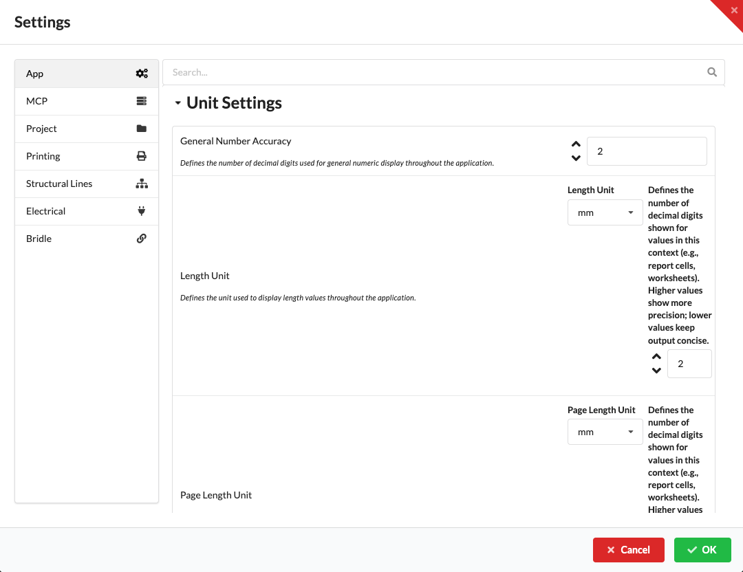
| Setting | Description |
|---|---|
| Rounding for numbers | Sets the number of decimal places for general numeric display throughout the application. |
| Unit for lengths | Sets the unit used to display length values throughout the application. |
| Unit for dimensions in print | Sets the unit for page and paper dimensions, as well as structural deflection values. This allows lengths to be displayed in meters and deflections in millimeters, for example. |
| Unit for area | Sets the unit used to display area values. |
| Unit for volume | Sets the unit used to display volume values. |
| Unit for weight | Sets the unit used to display weight values. |
| Unit for distributed weight | Sets the unit used to display weight per length, e.g., for distributed self-weight. |
| Force unit | Sets the unit used to display force values. |
| Unit for moment | Sets the unit used to display bending moment values. |
| Unit for distributed load | Sets the unit used to display distributed line-load values. |
| Unit for rotations | Sets the unit used to display rotational stiffness or moment per rotation angle. |
| Unit for percent | Defines how percentage values are displayed, either as 0 to 1 or as 0 to 100%. |
| Unit for power | Sets the unit used to display electrical power values. |
| Force per area | Sets the unit used to display force per area, e.g., pressure or wind-load intensity. |
| Unit for duration | Sets the unit used to display duration or timecode values. |
| Speed | Sets the unit used to display wind or movement speed. |
| Global transformation | Selects the coordinate reference for position entries in Object Properties. Global refers to the drawing coordinate system; local refers to the object or its parent object. You can switch between these modes in the Transform section using Change GCS/LCS. |
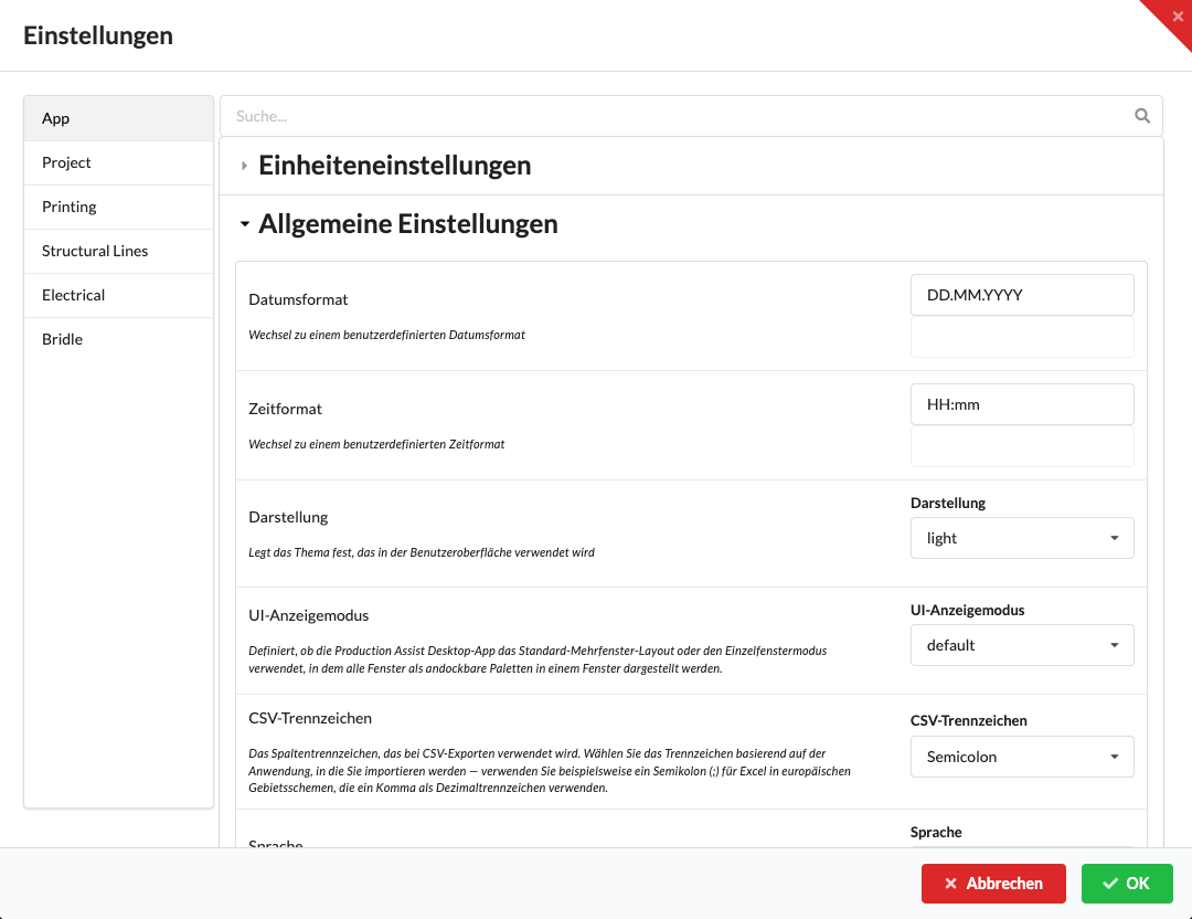
| Setting | Description |
|---|---|
| Date format | Determines how dates are displayed in the user interface. |
| Time format | Determines how times are displayed in the user interface. |
| Appearance | Sets the theme of the user interface. |
| UI display mode | Defines whether the desktop app works in multi-window layout or single-window mode with dockable palettes. |
| CSV delimiter | Determines the delimiter for CSV exports. For European Excel installations, ; is often useful. |
| Language | Sets the language of the user interface. |
| Show installed plugins at startup | Checks for compatible host applications at startup and offers plugin installation if needed. |
| Automatically group objects in assemblies | When enabled (the default), Production Assist automatically assigns objects that belong to connected structures to suitable assembly groups. The assignment may be adjusted when the structure changes. Turn this option off if you do not want Production Assist to adjust assembly groups automatically after structural changes. |
| Use Bridle Material Engine | Automatically adapts bridles to the selected bridle set and checks equipped rope paths in the background against the 3D geometry of other objects, even without static live calculation. If a collision occurs, it first attempts a suitable collision-free rebuild; only remaining collisions appear in the error list. Requirements and limitations: Check rope paths for collisions. |
| Log actions to a file | Writes application actions to a log file. This is especially useful for support and troubleshooting. |
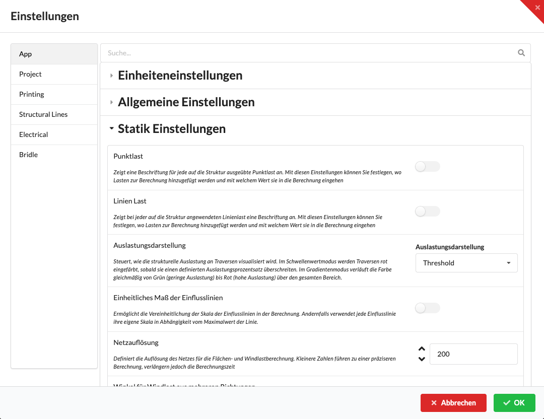
| Setting | Description |
|---|---|
| Point load | When enabled, a label appears in the drawing at each point-load position. This makes it easy to see where loads act on structural elements, what type of load is present, and their magnitude. Since many loads create many labels, this setting is mainly useful for checking the model; it is recommended to leave it disabled during normal use. |
| Line load | When enabled, a label appears in the drawing at each application point of a line load. This makes it easy to see where loads act on structural elements, what type of load is present, and their magnitude. Since many loads create many labels, this setting is mainly useful for checking the model; it is recommended to leave it disabled during normal use. |
| Utilization display | Defines how structural utilization is color-coded on trusses. Threshold Value: Utilization is shown only in green, yellow, and red stages; thresholds are freely configurable. Gradient Value: Color is interpolated continuously between 0% (green) and 100% (red), with 50% as yellow. |
| Uniform scale of influence lines | Controls the scale of influence lines in the calculation. When disabled, each influence line is scaled separately for visibility, usually to 1 m. For large bending moments (MBY = bending moment about the Y axis; MBZ = bending moment about the Z axis), this can result in uneven scaling of connections and make differences harder to see. When enabled, MBY and MBZ are always displayed at the same scale. |
| Mesh resolution | Determines the mesh size for area and wind loads (default: 100, minimum: 50). A smaller value gives a finer resolution and more precise results, especially when representing small geometry changes. The appropriate value depends on the geometry. Note that a smaller mesh size increases calculation time. |
| Angle for wind load from multiple directions | Defines the angle steps for multiple wind directions. Smaller steps are more accurate but require more computation time. |
| Use live statics calculation | Runs the static calculation automatically in the background after drawing changes. If you disable this option, you must start calculations manually. |
| Tolerance for loads for supports | Defines at what load share a load is assigned to a hoist. |
| Truss cross force as characteristic force | Shows the force of truss crosses as characteristic force without safety factors. |
| Assign loads to ground | Automatically assigns loads at height zero to the ground. |
| Disable partial calculation and abort calculation on errors | Stops the calculation immediately when a model error is detected. If disabled, Production Assist attempts a partial calculation of the remaining valid parts of the model. |
| Show FEA diagnostics | Shows technical FEM solver diagnostics in the error list and drawing. Enabled by default. When turned off, the actual structural errors, including instability after cable failure, remain visible. When turned on again, the saved diagnostics reappear. |
| Automatically generate truss crosses | Automatically creates suitable truss crosses. If disabled, you must create the connections manually. Whether a connection is suitable depends, among other things, on the position, direction, and permissions of the structural elements involved. The German interface spells “Trus” with one “s.” |
| Allow truss crosses in the same object | Off by default. When enabled, truss crosses can also be detected between structural elements of the same object. |
| Use pipes for AI placement of hoists | Determines whether pipes are considered as possible positions for support connections in Rigging → Place Hoists on Structure. |
| Automatically add truss cross in partial calculation | Includes truss crosses in a partial calculation when the structural elements they connect are also included in the calculation. |
| Show calculation summary after calculation | Opens the result overview after calculation is completed. |
| Automatically generate support object IDs | Automatically assigns object IDs for supports. |
| Calculate hoist utilization based on roof force | Uses roof force instead of hook force for utilization. |
| Hide load table explanation in structural reports | Hides the automatically generated explanatory text below load summaries in calculation reports. The load tables and manually written report text remain. This setting is off by default. |
| Use as drop for new bridle | Creates new bridle objects with drop option enabled by default. |
| Disable chain shortening compensation for new bridle | Disables automatic chain shortening compensation for new bridles. |
Create calculation results on level <None> | Places results on the default level instead of the active level. |
Create calculation results for class <None> | Places results in the default class instead of the active class. |
| Move calculation results to active class/level | Moves results to active level and class after each calculation. |
Custom name for the <None> level used for calculation results | Uses a custom level name for calculation results instead of the default level. |
Custom name for the <None> class used for calculation results | Uses a custom class name for calculation results instead of the default class. |
| Disable warnings about supports without weight | Suppresses warnings about supports without self-weight. |
| Disable warnings about supports without connection | Suppresses warnings about supports without connection. |
| Create truss cross in active class | Creates truss crosses in the active class instead of a named class. |
| Create truss cross in active level | Creates truss crosses on the active level instead of a named level. |
| Create truss cross in named class | Sets the target class for automatically generated truss crosses. |
| Create truss cross in named level | Sets the target level for automatically generated truss crosses. |
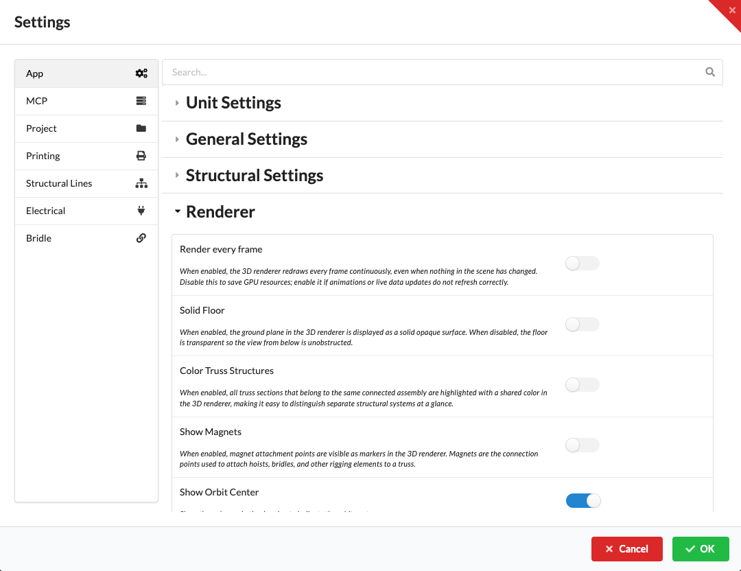
| Setting | Description |
|---|---|
| Continuous rendering | Continuously redraws every frame in the 3D renderer. This helps with live updates but requires more GPU power. |
| Render ground as opaque | Shows the ground plane as an opaque surface instead of transparent. |
| Color structures | Colors connected structures together in the renderer. |
| Show magnets | Shows magnetic connection points in the 2D and 3D renderers. The icon is also available in the 2D renderer's Quick Settings; its description appears when you hover over it or focus it with the keyboard. |
| Show orbit center | Briefly shows the orbit center as a red cross while rotating the 3D view. The cross disappears after the interaction. |
| Show grid | Shows the orientation grid in the 3D view. Turn it off if the grid lines obstruct the view of objects. |
| Show structure | Shows the structural geometry of structural elements in 2D and 3D. Turn it on to check the path of the load-bearing lines. Structural geometry remains visible in Edit Mode. |
| Show internal structure | Shows internal structural details, such as cross bracing, in the 3D view. They remain visible in Edit Mode even when this option is off. |
| 3D or 2D view | Switches between 2D and 3D display. |
| Hidden line display | Displays the 3D view as a high-contrast edge view. Surface colors are not shown as they are in the normal view. |
| Perspective camera view | Switches between perspective and orthogonal camera. |
| Show structural errors | Shows indications of structural errors in the 2D and 3D views. Use this option after a calculation to find affected locations in the plan. |
| Show labels for automatically generated supports | After a successful calculation, shows the X, Y, and Z forces on automatically generated supports in 2D and 3D, even when a force is zero. This option is enabled by default and is independent of Show structural errors. |
| Show ground supports | Shows or hides ground support geometry in the 2D and 3D views. It may remain visible in Edit Mode regardless of this switch. |
| Show floor support height | Shows a transparent orange horizontal plane at the Floor Level of the Settings profile. Off by default; visible only in the 3D renderer. The switch is also available under Display in Quick Settings. Move moves the plane vertically; the arrow is attached to the plane and moves with it. When you release it, the actual floor height is saved for the calculation. Done ends editing. The display does not enable Use floor as support or a clipping plane. Instructions: Show and move the floor height. |
| Show labels in 3D | Shows object labels in the 3D view. Also enable this option to see support results as 3D labels when Show result in 3D is enabled in the Object Properties of a chain hoist. |
| Show bridle element names in 3D | Shows the names of assigned bridle components on their rope sections in the PA renderer and in the native CAD model. Disabled by default and independent of global object labels; recalculating forces is not required. |
| Automatically adjust overlapping 3D labels | Moves overlapping labels on screen only so they are easier to read. The objects' saved label positions remain unchanged. This option affects labels in the 3D view. |
| Scale labels when zooming | Enlarges or shrinks on-screen labels when zooming in the 2D and 3D views. When this option is off, they retain a fixed size on screen. |
| 3D label font size | Sets the font size of on-screen labels in pixels. The value is also used for corresponding labels in the 2D renderer. When zoom scaling is enabled, the visible size also changes with the zoom. |
| Use device orientation | Orients the 3D camera according to the device's tilt and rotation. Orientation sensors must be available and supported by the runtime environment. If the browser requests sensor permission, you must grant it; if permission is denied, the renderer switch will not enable the feature. |
| Show coordinates in the 3D renderer | Shows or hides the coordinate display when using renderer tools. This option is enabled by default. |
| Disable snapping | Disables snapping to magnet points and other objects. |
| Enable auto-insert distance | Automatically adjusts the insertion distances to the X, Y, and Z extents of the selected structural geometry. This option is also available in the standalone Paste Offset window. |
| Fixture beam display | For fixtures with GDTF light data, chooses between Off (default; no light beam), Fast (simplified light beam), and Beautiful (detailed volumetric light beam). The choice affects graphics performance, but not calculations for trusses and pipes. |
| Small grid spacing | Defines the spacing of inner grid lines. |
| Large grid spacing | Defines the spacing of outer grid lines. |
| Always render renderer views | Renders embedded 3D views even while editing print layouts. |
| Zoom to cursor | Moves the zoom center toward the cursor position when zooming. |
| Enable cutting plane | In the 3D renderer, shows only geometry between the red start plane and the green end plane. The Clipping planes controls allow you to move them individually or together (Both), rotate them around the vertical axis, and fit them to the drawing. The model geometry remains unchanged. |
| Cutting plane distance | Sets the starting value for the red boundary along the cutting axis. Negative values are possible. |
| Cutting plane rotation | Sets the shared rotation angle of both parallel planes around the vertical Z axis. To rotate around the center of one boundary or the entire cut area, use Rotate in the 3D view. |
| Distance to cutting plane | Sets the ending value for the green boundary along the cutting axis. Only geometry between the start and end boundaries remains visible. |
The colored planes adapt to the drawing's size and position. The handles remain centered and the same size on screen while moving and zooming. Show clipping planes in the 3D controls hides the planes without turning off clipping; this display option is saved locally. Done hides the handles and makes object editing available again. The full instructions, with examples and troubleshooting, are in Inspect an interior area with the cutting plane.
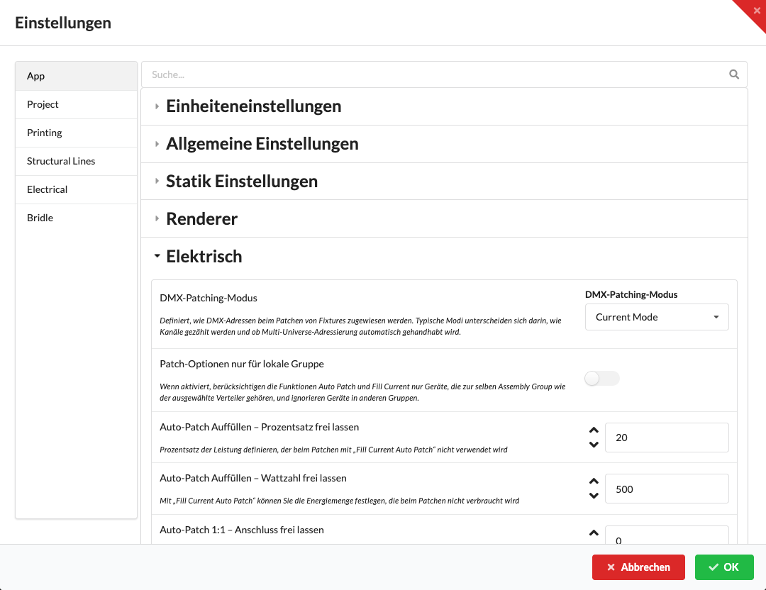
| Setting | Description |
|---|---|
| DMX patching mode | By default, uses Current Mode for a fixture's DMX footprint. Biggest Mode uses the fixture's largest available mode when patching. |
| Patch options only for local group | For an object in an Assembly Group, limits the selectable connections in Object Properties to that group. For an object without a parent assembly, the drawing-wide list remains available. This setting does not limit the automatic Patch Power 1:1 and Fill Power Patch commands. |
| Auto-patch fill—leave percentage free | Reserves a percentage of power when using fill-current auto patch. |
| Auto-patch fill—leave wattage free | Reserves a fixed wattage when using fill-current auto patch. |
| Auto-patch 1:1—leave connection free | Leaves a defined number of outputs free when using 1:1 patch. |
| Auto-patch mode | Controls whether reserves are managed in percent or watts. |
| Patch tool order | Sets the order for automatic power and data patch commands: by default, they follow the hierarchy in the Scene Tree; alternatively, they can follow position on the structure. The sort order selected for displaying the Scene Tree does not change this patch order. |
| Automatically resolve patch conflicts | Checks DMX addresses for collisions and automatically moves to free addresses if needed. |
| Color L1 | Sets the display color for L1. |
| Color L2 | Sets the display color for L2. |
| Color L3 | Sets the display color for L3. |
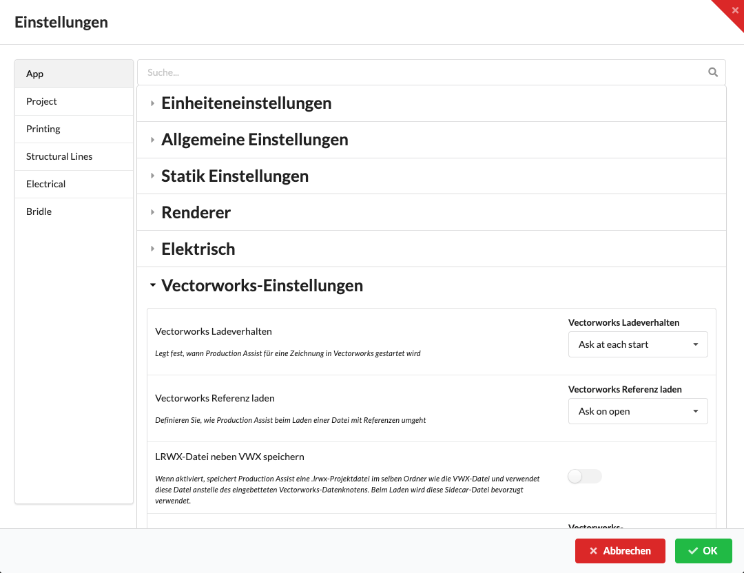
| Setting | Description |
|---|---|
| Save LRWX file next to VWX | Saves the Production Assist drawing as a same-named .lrwx file next to the saved VWX file instead of embedding it in Vectorworks. Pass on both files when sharing. When loading, the LRWX file takes precedence if this option is enabled; otherwise, the embedded data is used. If the preferred data is missing, the other is used. |
| Vectorworks tessellation quality | Sets the mesh resolution when importing geometry from Vectorworks. You can use the document setting or a fixed resolution from low to very high. Finer meshes represent curves in more detail, but require more memory and processing time. |
| Ignore Vectorworks symbols | Skips Vectorworks symbol instances when reading and synchronizing. Use this option if these instances should not be imported as Production Assist objects. Enabling the option does not remove objects that have already been imported from the drawing. |
| Limit number of labels in Vectorworks | Limits error labels drawn in Vectorworks to a maximum of 201 error entries. This limit is fixed and cannot be set as a number. It does not resolve additional errors; continue to check all messages in the Production Assist error list. |
| Vectorworks load behavior | Defines when Production Assist is used for a Vectorworks drawing. Ask at each start (default) asks while reading the drawing whether Production Assist should use it. Always Use uses Production Assist automatically without asking. Manually Enable does not start Production Assist automatically. With Ask at each start, the choice in the dialog applies to that read operation. |
| Load Vectorworks reference | Controls how external reference files are handled when opening. Typical options are: Prompt — asks whether to load references when opening; Always — loads references automatically; Manual / Ignore — does not load references automatically. If references are loaded, Production Assist can use their geometry to build the model and perform calculations; automatically loading large references can increase load time and memory usage. |
| Disable Vectorworks patch integration | Turns off patch integration with Vectorworks: Production Assist then no longer reads or writes channel, dimmer, or patch fields in Vectorworks objects. This prevents patch data (e.g., channel/dimmer) from being accidentally overwritten if it is maintained manually in Vectorworks or managed by other tools. |
| Disable data tag coloring | Disables automatic coloring of hoist data tags by workload. When this option is enabled, data tags are no longer color-coded by workload—useful when a uniform display or an external color scheme is desired. |
| Overwrite empty connections | Deletes pseudo-connections without a counterpart object. |
| Always generate calculation results | Controls the display of existing calculation results in Vectorworks. When enabled, Production Assist creates separate classes for each type of section reaction and displays utilization even if its checkbox in the calculation result object is unchecked. Other result types continue to follow their respective checkboxes. When disabled, results are displayed in a shared class, and utilization also follows its checkbox. Disabled by default. |
| Show support results in weight | When printing hoist labels, produces values in weight units (e.g., kg or lb) instead of force (kN). Useful when labels should show the weight to be lifted instead of the resulting force. |
| Show hook force as load result | For hoist labels, shows the hook force (force at the hook, e.g., in kN) instead of the roof/truss force. Helpful when selecting lifting equipment and checking the load at the hook. |
| Show chain shortening as hoist result | Shows the entered chain shortening value on hoist labels (if it is not zero). Useful for documentation and checking; the display can be disabled if needed. |
| Insert errors in active class | Automatically places error objects in the currently active class. When enabled, newly created error objects are automatically moved to the active class when they are created or when the active class changes. |
| Insert errors in class | Places error objects in a named (fixed) class. This setting is effective only when Insert errors in active class is disabled; otherwise, the active-class option takes precedence. |
| Insert errors in active layer | Automatically places error objects on the currently active layer. When enabled, newly created error objects are automatically moved to the active layer when they are created or when the active layer changes. |
| Insert errors in layer | Places error objects on a named (fixed) layer. This setting is effective only when Insert errors in active layer is disabled; otherwise, the active-layer option takes precedence. |
| Synchronize position entry | Synchronizes the position field with Vectorworks. When enabled, position data from Vectorworks is transferred to the position field in Production Assist. When disabled, the position field remains unchanged and no automatic transfer occurs. |
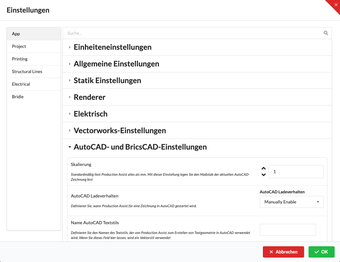
| Setting | Description |
|---|---|
| Insert with double click | Requires a double-click to insert in the native DWG Library window. When disabled, a single click is sufficient. Enabled by default. |
| Hide after insertion | Hides the native DWG Library window when insertion starts. When disabled, the window remains visible so you can select another block. Enabled by default. |
| Scaling | Sets the scaling factor for converting drawing units to internal millimeters. Production Assist works internally in millimeters. Example: If DWG units are meters, enter 1000 (1 m = 1000 mm). If DWG units are already millimeters, enter 1. |
| AutoCAD load behavior | Applies when opening a DWG in AutoCAD and BricsCAD. The default is Manually Enable: the plugin loads, but the drawing is activated only with Enable PA. Ask at each start asks whether to activate each drawing; Always Use activates it automatically when opened. Use Disable PA to stop synchronization for the active drawing. This selection controls drawing activation; whether model changes automatically trigger a calculation is set separately with Real Time ON/OFF. |
| AutoCAD text style name | Sets the text style for general text geometry in AutoCAD. |
| AutoCAD text style name for FEM model—bar | Sets the text style for bar labels in the structural model. |
| AutoCAD text style name for FEM model—line loads | Sets the text style for line load labels in the structural model. |
| AutoCAD text style name for FEM model—nodes | Sets the text style for node labels in the structural model. |
| AutoCAD text style name for FEM model—point loads | Sets the text style for point load labels in the structural model. |
| AutoCAD text style name for influence line values | Sets the text style for influence-line result value labels, including force, moment, deflection, and utilization labels. |
| AutoCAD text style name for script labels | Sets the text style for script labels. |
| AutoCAD PDF export resolution | Sets the resolution (DPI) for exported PDFs and embedded raster images. Default is 72 DPI; higher values provide sharper exports but increase file size and render time. |
| Save LRWX file next to DWG | Enabled by default. When saving a DWG with Production Assist active, an additional project file is written to the same folder, for example, Plan.dwg.lrwx next to Plan.dwg. When reopened, the plugin loads this file if it exists. For a reliable Production Assist project state, provide both files together. Depending on the project configuration, the DWG may also contain application-specific additional data; this does not replace the LRWX file for restoring the complete project state. This option does not prevent an existing LRWX file from being loaded. Automatic CAD backups do not update the LRWX file. |
| Load XREFs | Enabled by default. Reads external reference drawings (XREFs) and includes their geometry in static calculation. When disabled, attached and overlaid XREFs, including their contents, are ignored during reading and synchronization, even when nested inside a regular block. XREFs remain visible in AutoCAD and BricsCAD; this option controls only their adoption into Production Assist. XREFs that have already been bound are treated like regular blocks. |
| Import all AutoCAD blocks | Also creates symbol objects for block references without recognized PA data, such as assigned attributes or structural lines. Disabled by default; otherwise, these blocks are skipped. |
| Prefer structural lines over symbol mappings | Disabled by default. If a newly adopted block contains both an entry in the Symbol Map and valid geometry on assigned Structural Lines layers, enabling this option gives priority to the structural, support, and load data from the block. Changing this setting does not convert objects that have already been adopted. |
| Align text to screen layer | Aligns generated text with the screen plane instead of the global plane. When enabled, all labels in the structural model are aligned with the screen plane, which is useful for screenshots and plot output because the text remains readable and correctly positioned in the image. |
| Randomly color bars | Assigns random colors to FEM/truss bars instead of one uniform color. This makes individual bars easier to distinguish, which is useful for checking, debugging, screenshots, and plotting. |
| Show load number in structural model | Displays load numbers in the structural model. |
| Show bar length in structural model | Displays bar lengths in the structural model. |
| Show load unit in structural model | Shows the unit next to load values. |
| Show support reaction unit in structural model | Shows the unit next to support forces. |
| Show bar length unit in structural model | Shows the unit next to bar lengths. |
| Show line and point load at same scale | Forces the same display scale for point and line loads. |
Enter the name of a text style present in the DWG in the AutoCAD text style name or individual AutoCAD text style name fields. If a field is left blank, Production Assist uses a default vector text style so labels remain visible.
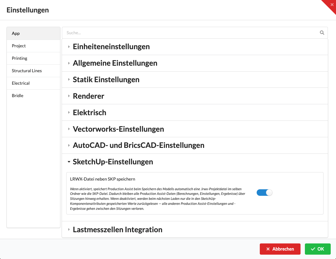
| Setting | Description |
|---|---|
| Save LRWX file next to SKP | When synchronization is active, saves the Production Assist drawing as a same-named .lrwx file next to the SketchUp model. The model must already be saved to a file path. Provide the SKP and LRWX files together. Without this option, the LRWX file is not updated. An existing LRWX file can still be loaded when opening, and may then contain an older state. |
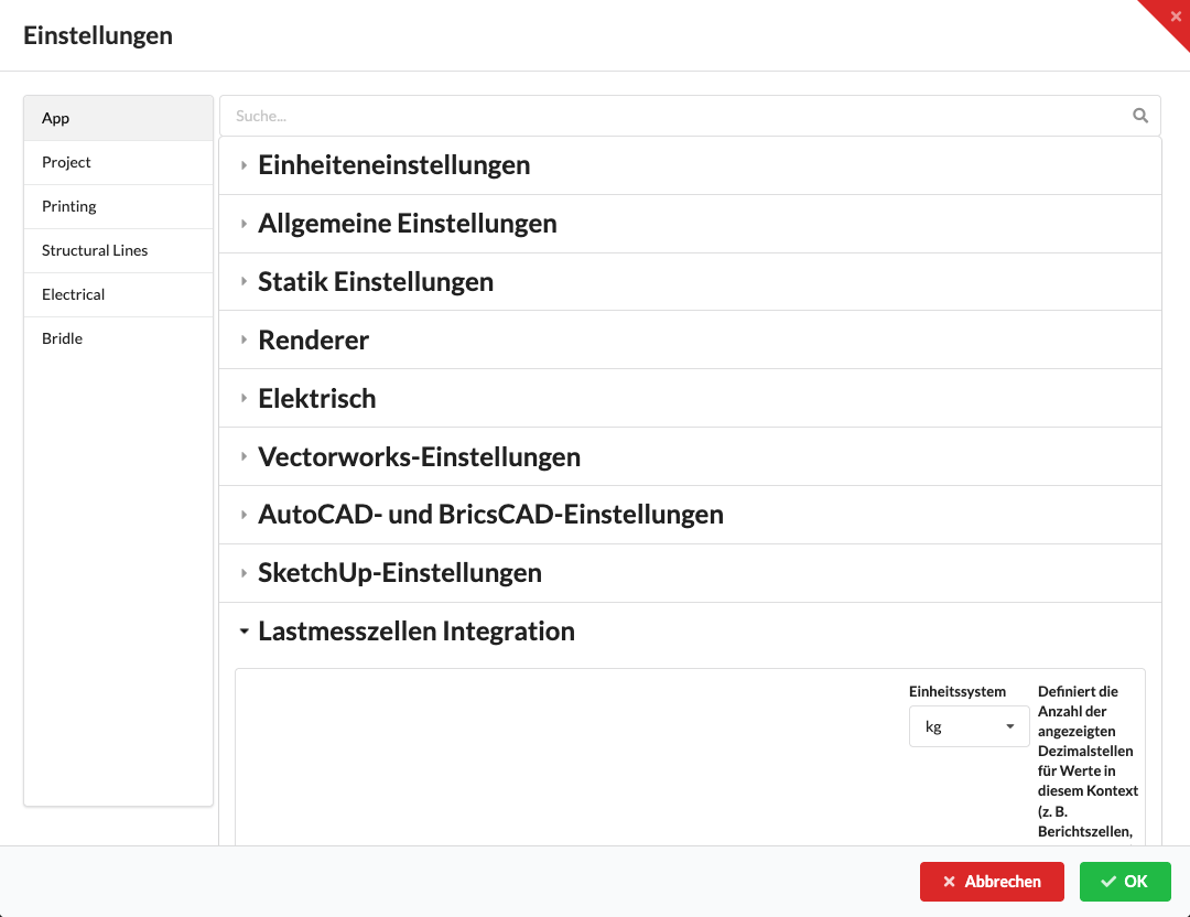
The example view is synthetic and shows an unsuitable help text beside Unit system. This setting determines the weight unit for Broadweigh load cells; the selected unit must match the measuring hardware or LOG100.
| Setting | Description |
|---|---|
| Unit system | Sets the unit in which Broadweigh load cells provide their measurements. Choose the same unit as in the measuring hardware or LOG100 software. |
In the Project section, you enter the master data for the current drawing. This information is used in reports, PDFs, metadata, and project overviews.
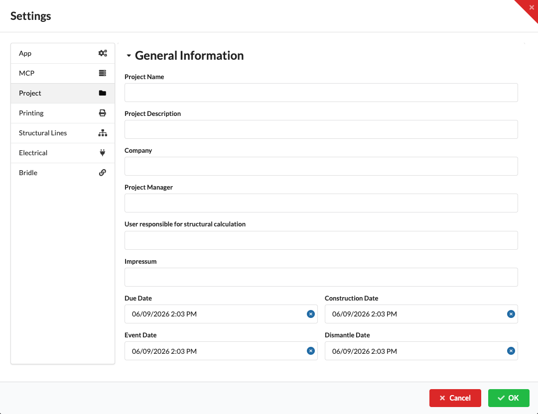 The General Information and Location Information sections can be expanded. Edit the fields in the relevant section and confirm changes in the settings dialog with OK. Project fields are unavailable when no drawing is open.
| Field | Meaning |
|---|---|
| Project Name | Name of the project. This value appears in reports, overviews, and exports. |
| Project Description | Free text describing the project or construction. |
| Company | Company or client for the project. |
| Project Manager | Person responsible for coordinating the project. |
| User responsible for structural calculation | Person responsible for the structural calculation. |
| Legal Notice | Legal notice or text that can be included in documents. |
| Due Date | General due date for the project. |
| Construction Date | Planned or actual setup date. |
| Event Date | Date of the event. |
| Dismantle Date | Planned or actual dismantling date. |
| Field | Meaning |
|---|---|
| Venue | Name of the event venue. |
| Street | Street of the venue. |
| Number | House or building number. |
| Postal Code | Postal code of the venue. |
| City | City of the venue. |
| Country | Country of the venue. |
In the Printing section, you define how reports, worksheets, and PDF output are formatted. This includes paper sizes, margins, text styles, and table layouts.
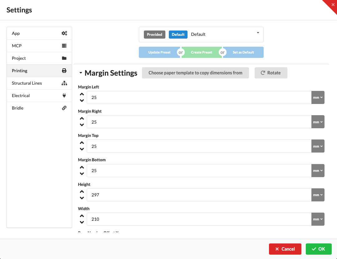
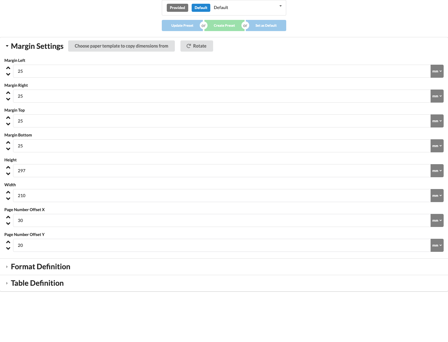
Select a preset, adjust the paper size, margins, text styles, or table layout, and confirm with OK to apply the settings to the current drawing. Update Preset overwrites the selected custom preset with the current values. This button is disabled if the values have not changed or if a supplied preset is selected. Create Preset becomes available when the values differ from the selected preset. Set as Default determines which preset is assigned to new projects by default. Supplied presets cannot be overwritten or deleted. Delete custom presets using the red delete icon in the preset menu; the application then switches to the Default preset.
At the top of the Printing section, you work with print presets:
| Element | Meaning |
|---|---|
| Preset selection | Selects the print format currently being edited. |
| Standart / Benutzer | Marks a supplied preset or one set as the default with Standart, and a custom preset with Benutzer. The spelling Standart matches the label in the current interface. |
| Update Preset | Overwrites the currently selected custom preset with the current values. This action is disabled for supplied presets or when the values have not changed. |
| Create Preset | Opens the dialog for saving the current format values under a new name. This action is disabled while the values are unchanged. |
| Set as Default | Sets the selected preset as the default for new projects. |
You can change a custom preset using Update Preset or delete it using the red delete icon in the preset menu. Deletion does not require an additional confirmation. Supplied presets are read-only.
Creating, updating, deleting, and setting a default preset are saved immediately. Selecting Cancel in the parent settings dialog does not undo these preset actions. Continue to confirm changes to the other printing settings with OK.
| Field | Meaning |
|---|---|
| Margin Left | Left margin for printed reports and PDF output. |
| Margin Right | Right margin for printed reports and PDF output. |
| Margin Top | Top margin for printed reports and PDF output. |
| Margin Bottom | Bottom margin for printed reports and PDF output. |
| Height | Paper height for reports and PDF output. |
| Width | Paper width for reports and PDF output. |
| Page Number Offset X | Horizontal offset of the page number. |
| Page Number Offset Y | Vertical offset of the page number. |
| Select a paper template to copy dimensions from | Opens the dialog for applying page dimensions and margins from an existing paper template. |
| Rotate | Swaps width and height to rotate the paper format. |
Applying the template also sets the page number offsets to 30 mm (X) and 20 mm (Y). Check these two values afterward if you have already set custom page number positions.
In Format Definition, you define the typography of reports. Each tab represents a separate text style.
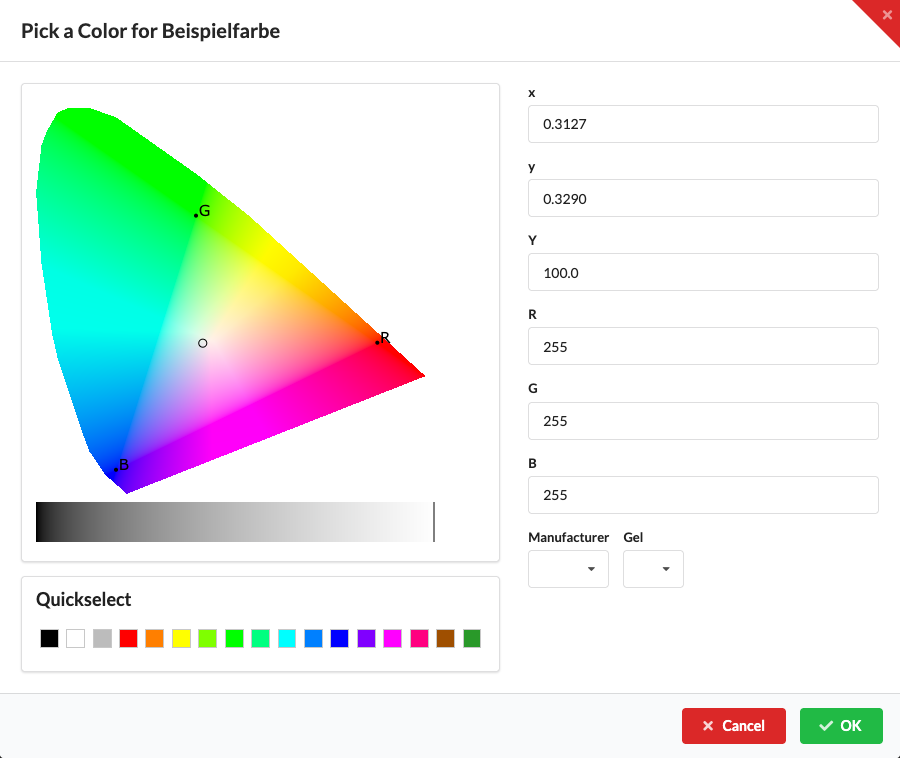
The pen icon next to Text Color opens the Choose a color dialog. Adjust the color and confirm with OK; Cancel discards the selection. The image shows the shared color picker component with sample values. The additional text in its title is not part of this settings dialog.
| Tab | Meaning |
|---|---|
| H1 | Style for first-level headings. |
| H2 | Style for second-level headings. |
| H3 | Style for third-level headings. |
| H4 | Style for fourth-level headings. |
| Text | Style for body text. |
| Footer Text | Style for footer text. |
| Cell Header | Style for table header cells. |
| Table of Content H1 to H4 | Style for table of contents entries at each hierarchy level. |
The following fields are available for each style:
| Field | Meaning |
|---|---|
| Font Name | Sets the font family. |
| Font Size | Sets the font size. |
| Text Color | Sets the text color. |
| Space Before | Spacing before the text block or paragraph. |
| Space After | Spacing after the text block or paragraph. |
| U / B / I | Enables underline, bold, or italic for the selected style. |
In Table Definition, you define the appearance of tables in reports.
| Element | Meaning |
|---|---|
| Custom settings for outer table borders | If enabled, the table's outer border is rendered using custom settings. |
| Alternate cell coloring | If enabled, every other row uses its own cell style. |
| Table Outline | Style for the outer table border. |
| Headers | Style for table header cells. |
| Group Headers | Style for grouped headings across multiple columns. |
| Cells | Standard style for data cells. |
| Interleaving Cells | Style for alternating data rows. |
| Line Style | Defines the border line style. |
| Line Color | Defines the border line color. |
| Line Width | Defines the border line width. |
| Padding | Defines the spacing between content and border. |
| Cell Color | Defines the cell background color. |
| Copy from previous side | Applies the border settings from the previously edited side. |
| Apply to all sides | Applies the current border settings to all sides. |
| Top / Left / Right / Bottom / Content | Selects which border edge or content area is being edited. |
In Structural Lines, you specify which CAD layers or classes are treated as structural elements, supports, or loads in the static calculation. This lets you add a calculable line and point model to an existing symbol or block: draw the statically relevant geometry in the symbol or block definition and assign it here. In Vectorworks, use classes for this; in AutoCAD, BricsCAD, and other CAD integrations, use the corresponding levels or layers.
The assignments determine which static properties Production Assist derives from the geometry. For example, a structural line receives the assigned cross-section; support points and load geometry are interpreted according to their respective layer or class assignments. If you edit a symbol or block that is already in use, update the affected instances or read the drawing in again so Production Assist picks up the changed definition.
The connections you draw are also part of the model: two lines that only cross are not automatically considered connected. To form a node, a line endpoint must lie on the adjoining line or on a shared endpoint. Examples of connected and merely crossing lines are in AutoCAD: Structure by Line. Structural Lines in a Vectorworks Symbol describes a complete Vectorworks symbol workflow; LED Wall with Structural Lines shows an end-to-end modeling example.
Use Save Structural Lines as Default to save the current assignments for Structure Layers, Support Layers, and Load Layers as a local preset. When opening drawings, Production Assist uses these assignments to add layer assignments that are not yet present. Assignments already saved in a drawing with the same layer name remain unchanged. The preset is saved locally on your computer and is not part of the drawing file. Saving does not change the drawing that is already open. To apply the edited assignments to the current drawing as well, confirm the settings dialog with OK.
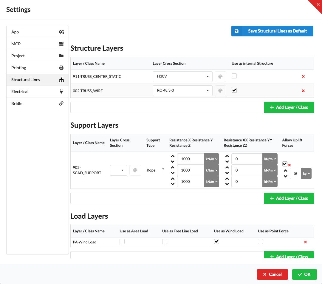
The image shows Structure Layers, Support Layers, and Load Layers together. The names and assignments are UI examples.
| Field | Description |
|---|---|
| Layer / Class Name | CAD layer whose curve geometry in placed blocks is read as structure. |
| Cross Section | Cross-section for the recognized structural elements; Use from Geometry is an option in the cross-section field. |
| Define as Internal Structure | Marks the generated structural elements as internal truss members. To have the calculation use these instead of the centerline structure, you must also enable Calculate Internal Members in the Settings profile. |
Create lines or other curve geometry in the CAD block on an assigned layer. When the placed block is read in, Production Assist creates structural elements from it. Then check that the cross-section and connections in the recognized model are correct.
Important rules and options:
By default, Production Assist calculates the normal global centerline structure. Internal geometry is considered only if Calculate Internal Members is also enabled in the Settings profile under Navigation → Load Combinations → Load Combination Settings. If this option is off, the prepared symbol is calculated as a simplified centerline model. If it is on, the calculation uses the truss members marked as internal for those symbols instead of the simplified centerline model. This lets you calculate the same structure once as a truss or equivalent member using the global centerline structure, and once using the individual chords and braces through the internal structure. For this, the symbol must contain internal structural geometry on the assigned layers.
The separate renderer option Show Internal Structure controls only whether internal geometry details are visible in the 3D renderer. It does not enable their calculation.
| Field | Meaning |
|---|---|
| Layer / Class Name | Name of the CAD layer. |
| Cross Section | Assigned cross-section or the Use from Geometry option. |
| Palette icon | Opens the color mapping for the selected cross-section. |
| Define as Internal Structure | Marks geometry as internal truss members. Calculate Internal Members in the Settings profile controls whether they are calculated instead of the normal centerline structure. |
| Delete icon | Removes the layer assignment. |
| Add Layer / Class | Adds another assignment; names that already exist are not added a second time. |
Here you define which layers or classes are interpreted as supports and how they are handled in the calculation. The following points are important:
| Field | Meaning |
|---|---|
| Layer / Class Name | Name of the CAD layer. |
| Cross Section | Cross-section for the rope if the support layer contains a line. |
| Support Type | Type for points on this layer; lines are always created as ropes. |
| Resistance X / Y / Z | Translational stiffnesses for point supports. |
| Resistance XX / YY / ZZ | Rotational stiffnesses for point supports. |
| Allow Uplift Forces | Allows uplift forces at point supports. |
| Capacity | Capacity of the support or rope; the field is below the checkbox. |
| Delete icon | Removes the support assignment for this layer. |
| Add Layer / Class | Adds another support assignment. |
Here you define how geometry on a CAD layer in placed blocks is read as a load. The assignment alone does not create a load: the block must contain suitable lines, curves, or points on the listed layer. The current image shows the Structure Layers, Support Layers, and Load Layers areas together. If no load type is enabled, a line is adopted as the path for a line load.
The default assignments are PA-Line Load (line load, with no checkbox selected), 911-AREA_LOAD and PA-Area Load (area load), PA-Wind Load (wind load), PA-Point Force (point force), and PA-Free Line Load (free line load). A newly added layer initially has no load type enabled.
| Field | Meaning |
|---|---|
| Layer / Class Name | Name of the CAD layer in the block definition. |
| Use as Area Load | Curve geometry on this layer is adopted as an area-load surface; use a closed polygon for an area. |
| Use as Free Line Load | Curve geometry on this layer is marked as a free line load. |
| Use as Wind Load | Curve geometry on this layer is marked as a wind-load surface; use a closed polygon. |
| Use as Point Force | Points on this layer are adopted as point-force geometry. Set the force components on the object. |
| Delete icon | Removes the load assignment for this layer. |
| Add Layer / Class | Adds another load assignment. |
In Electrical, you define the default connectors that are preselected when creating new devices or connections.
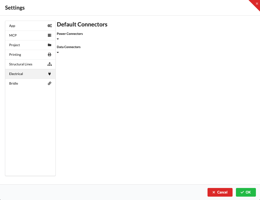
| Field | Meaning |
|---|---|
| Power Connectors | Defines the default power connector for new electrical devices. |
| Data Connectors | Defines the default data connector for new devices or network connections. |
The dropdowns can be searched. Select a connector from the appropriate list in each dropdown and confirm with OK. These defaults apply to newly created devices or connections; they do not change existing connectors.
For more on the basics of electrical planning, see Electrical Planning.
In Bridle, you set the rope safety distance as well as standard parts and presets for new bridles. A saved bridle parts preset stores which parts from a selected Bridle Set should be available when creating new bridles. Preferred Basket Part marks the preferred part for the basket. This selection controls the parts available for new bridles; assign the static properties of a symbol or block separately under Structural Lines.
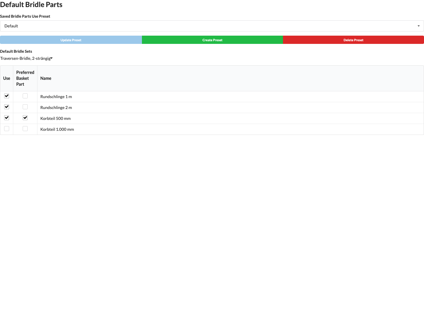
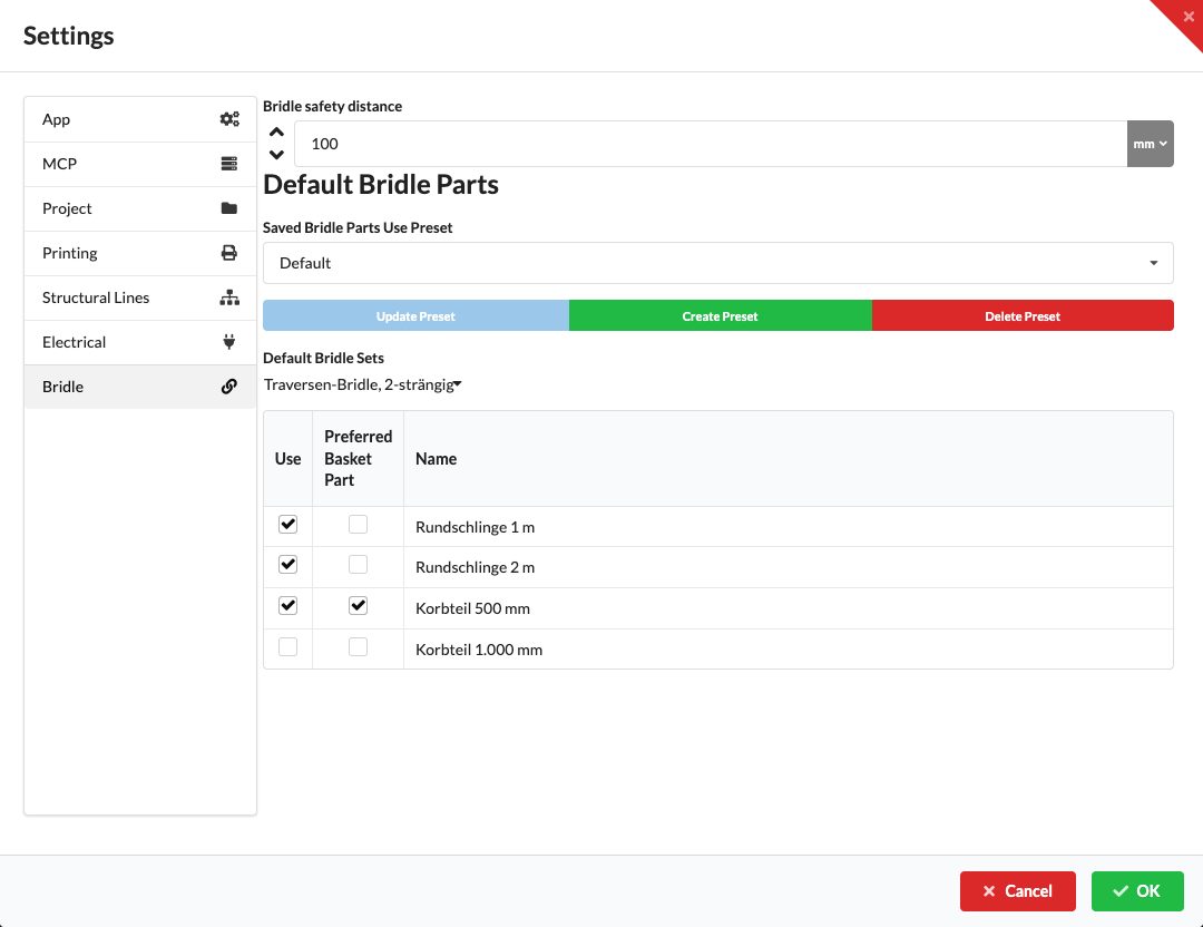
The screenshot still shows the English field label Bridle safety distance.
First select a Saved Bridle Parts Use Preset and its associated Default Bridle Set. In the parts list, use Use to choose which parts Production Assist should consider when creating new bridles. Preferred Basket Part marks a part as the preferred option for the Basket. Confirm the changes in the settings dialog with OK.
The names shown in the renderer screenshots are sample data and do not have to exist as resources in your drawing. In your drawing, select the Bridle Set whose parts you actually want to make available for new bridles.
Bridle safety distance determines the distance between the straight rope axis and the 3D surface of other objects. The default value is 100 mm. The value applies to all bridles in the application, including already assembled runs and drops. The input uses your configured length unit; negative distances are not allowed. At 0 mm, only actual collisions are checked. Apply the value with OK.
When Use Bridle Material Engine is enabled, Production Assist checks the distance in the background and, if there is a conflict, first attempts a suitable rebuild with sufficient clearance. An error message appears only if this is not possible. Objects to which the respective run is connected at its start or end are excluded. Requirements and limitations are explained in Check rope path for collisions and safety distance.
| Element | Meaning |
|---|---|
| Saved Bridle Parts Use Preset | Selects a saved parts selection and its associated Bridle Set. |
| Update Preset | Saves the changed parts selection to the selected preset. |
| Create Preset | Opens the Create Preset dialog, where you enter a name for a saved bridle parts preset. |
| Delete Preset | Deletes the selected parts preset without an additional confirmation prompt. Check the displayed name before deleting it. |
The images above show the preset selection and how to open it, not the open dialog.
When creating the preset, the current interface sends an empty list of disabled parts; after creating it, you can check and adjust the parts in the table. Creation also uses the name from Saved Bridle Parts Use Preset as BridleSetName; it does not read the separately selected value under Default Bridle Sets. How this determines the set assignment is not reliably known. Therefore, check the assignment after creating the preset before using it for new bridles.
Creating, updating, and deleting a bridle parts preset are saved immediately. Cancel in the parent settings dialog does not undo these actions. Confirm changes to the parts selection and the default Bridle Set with OK.
| Field | Meaning |
|---|---|
| Default Bridle Sets | Selects the Bridle Set whose parts you are editing in the table. The parts selection is used as a preset for new bridles. |
| Use | Enables or disables the part for new bridles. |
| Preferred Basket Part | Marks the preferred basket/sling part for the Bridle Set. Available parts and suitable lengths depend on the selected set and the available resources. |
| Name | Shows the name of the part or symbol; used to select and identify the geometry element. |
For more on the basics of bridle calculations and structural checks, see Static Calculation.