

MVR (My Virtual Rig) is an open exchange format for 3D models and planning data between CAD programs, visualizers, and lighting consoles. This quick start shows you how to import an MVR file, add missing Production Assist data through the Symbol Map, and transfer a revision over the local network using MVRxchange.
Which information is transferred also depends on what the exporting application writes to the MVR file. Production Assist can import included structures, fixtures, supported GDTF data, and connections. If this information is missing from the export, it cannot be derived from the drawing during import. You can assign incoming symbols to matching Production Assist symbols to add it.
.mvr file on your computer.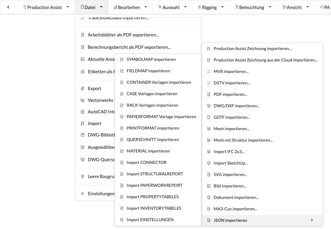
The menu view shows the current entry point for importing. For a full description of MVR and GDTF file workflows, see the GDTF and MVR workflow.
The Symbol Map shows the symbols Production Assist found in the MVR file. Each row shows the incoming symbol name on the left. On the right, select a matching Production Assist symbol using Edit. This adds properties from the Production Assist resource to a simple incoming symbol, such as Structure, Support, electrical, or Audio elements.
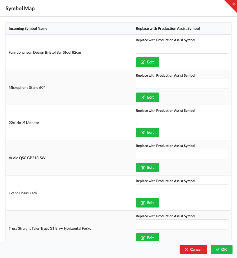
Choose a mapping if you want to use a matching Production Assist resource for the incoming object. The Edit dialog offers Online Drawing and User Resources. An online resource may need to be downloaded first. The mapping is saved for later imports. For details on managing mappings, see Symbol Map in the Resource Manager.
Import Groups is enabled by default. Leave it on to import groups from the file as Assembly Groups in the Scene Tree. OK continues the import with the selected mappings. Cancel closes the dialog without importing this MVR file.
Production Assist imports supported content when it is present in the MVR file. The source file must export it; options and defaults vary between CAD programs, visualizers, and consoles.
| Content | What Production Assist can import |
|---|---|
| Drawing structure | Layers, classes, groups, and the supported MVR objects they contain, such as fixtures, trusses, and general Scene Objects. |
| Geometry | MVR symbol and mesh geometry, as well as geometry from embedded GDTF files. |
| GDTF fixtures | Fixture Type, mode, device geometry, and transferred device values such as Fixture ID and DMX addresses. |
| Structure and supports | Structure, cross-section, and Support information when the referenced GDTF file contains these supported elements. |
| Electrical and network data | GDTF connectors and their properties, as well as their connections, when the exporting application writes compatible connector and connection data to the MVR file. |
| Audio | Audio devices may arrive as general MVR objects with a name and geometry. Add or check the special Production Assist Audio designation by assigning a matching symbol or after importing. |
| Inventory and other symbol data | Supported GDTF elements, if they are present in the file. |
For a complete GDTF fixture, device geometry, modes, and supported electrical connections are usually already linked to the MVR file. Production Assist then reads this information during import. Still check after importing that the values and connections are complete for your project. If the exporter omits GDTF or connection data, that information will also be missing in Production Assist.
The Audio element marks an audio object and the position of its audio source in a Production Assist symbol definition. If needed, assign the incoming symbol a matching Production Assist resource with this element in the Symbol Map, or add it to the symbol definition after importing. The Audio element section describes how it works.
Replacing symbols is especially helpful when the source file exports only simple symbols with names and geometry. Select the matching Production Assist resource so that required production data, such as structural members, supports, or connections, is available in the drawing. This does not replace values that are missing from the selected resource as well.
MVRxchange is the network protocol for exchanging MVR revisions through a local network service. Use it when several MVRxchange-enabled applications are working on a plan on the same accessible local network. Participants connect to the same group and publish or download named drawing states. Changes become visible after one participant publishes a new revision and another imports it.

The image shows the dialog before connecting. After joining, the published and externally available revisions also appear. A revision from another participant is visible only after they publish it. For the full workflow, network interface, and troubleshooting, see MVRxchange on a local network.
Open the Scene Tree and check that the expected layers, groups, and objects are present. For trusses and other load-bearing objects, check that the structure information is correct. For fixtures and distributors, check the transferred connections in the Electrical View, as well as device and connection values in Object Properties.
If data is missing, first check whether the exporting application wrote it to the MVR file. You can use the Symbol Map to add missing symbol definitions. For more information about structural members and electrical connections, see the symbol workflow, and for power and network wiring, see electrical planning and network planning.