

The Renderer displays the geometry of objects in your drawing. Use Layers and Classes in Navigation to control which objects are visible. You can select objects in the Renderer and edit them with tools from the Toolbar; their arrangement is shown in the Scene Tree.
In the desktop app, the 2D, 3D, Beam, Bridles, Truss Builder, and Bridle Builder buttons are at the upper right of the Renderer. Select 2D for the plan, 3D for the spatial view, or Beam to inspect individual structural beams and their loads. Truss Builder and Bridle Builder open dedicated creation views that hide the general editor panels. The Creation workspace menu in the footer opens the same views, even when the Renderer panel is closed. Use Full editor to return to the previous editor layout and Renderer view. In the mobile footer, the views are available as labeled buttons. In the browser, a button below the Renderer cycles from 3D to 2D, Beam, Bridles, Truss Builder, and Bridle Builder, then back to 3D.
After the first opening, the 2D and 3D views remain in the same Renderer. When switching back, the respective view and zoom are retained. Changes to the drawing are applied before the view is used again; a loading indicator may briefly appear. After a full reload, the display must be rebuilt.
Use the 2D view to inspect the floor plan, support positions, and forces in the plane. You can zoom to the pointer independently of the 3D camera and pan with two fingers on the trackpad. The example below shows a truss with four suspensions and calculated support forces.
When opening the 2D view, the loading indicator remains active until the first display and any active editing mode have been set up.

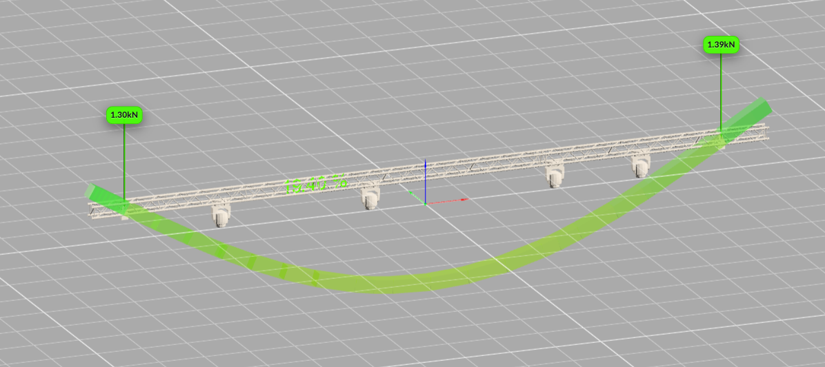
The 3D view shows the spatial structure and can display calculated deformations and support forces. Use it to assess the spatial positions of members and the shape of a deformation. The example shows a truss with a green deformation display and support forces.
View → Isometric View or the default V shortcut toggles the perspective camera view. The same option is called Perspective Camera View in settings. The C shortcut instead selects objects with the same name within an assembly group. See Keyboard Shortcuts in Production Assist for more shortcuts and how to customize them.
The Beam view shows the length, supports, loads, and—if available—calculated section reactions of individual structural beams. Use it to inspect and adjust their positions along a beam.
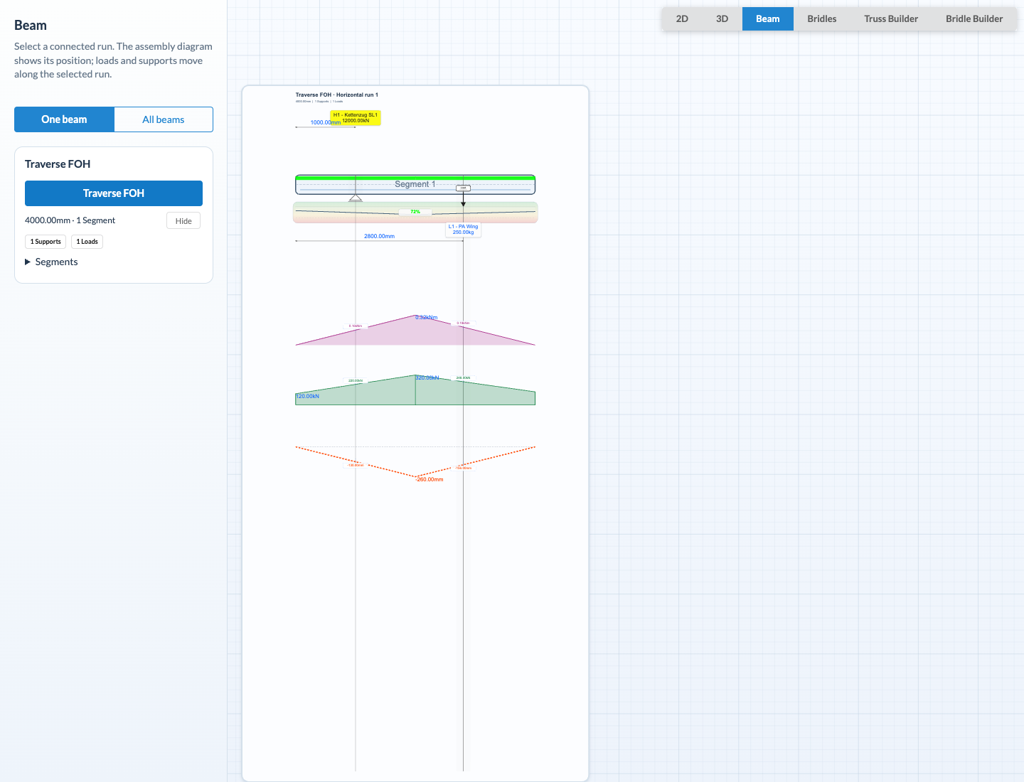
For detailed instructions on connecting to drawing objects, moving loads and supports, and viewing section reactions, see Beam View in the Renderer.
Bridles shows individual or all two-, three-, and four-leg bridles with lengths, angles, and the parts used. Planned and Built from parts compare the planned geometry with the assembly made from the selected part lengths at the same scale. If you raise the blue planned junction point, a drop is added or adjusted to the fixed lower load point. Automatic assembly can combine shorter upper ropes with a drop and shows any remaining length deviations. The upper attachment points and lower load point remain fixed. Arrange the bridles using the headers within the same parent object, or open the part editor for a leg. The order follows the normal drawing hierarchy and is also visible in the Scene Tree. Changes to parts and junction height remain in a preview until Apply changes; Cancel discards them. See Bridle View and Assembling Parts for instructions.
Bridle Builder creates and edits two- and three-leg bridle systems with actual attachment points and an actual load in the current drawing. There, you can delete a selected system after confirmation; a recognized associated load is deleted with it, while other objects in the same assembly remain. The inputs, automatic material assignment, and calculation display are described in the Bridle Builder instructions. The full overview and part editing, including four-leg bridles, remain available under Bridles.
Truss Builder creates a straight structural truss run with a selected cross section as an assembly in the current drawing. It is a parametric structural run, not an arrangement of manufacturer segments. Select New truss run, enter a name, cross section, and length, then confirm with Create truss run. The first run extends horizontally from the drawing origin. Each subsequent run is placed parallel in the +Y direction, 2 m above the highest existing run. It appears in the list even without a prior calculation. Length and spacing labels follow the selected length unit.
For an existing run, enter the length in the Inspector or move the end handle with a mouse or touch. The start remains fixed. Loads already placed keep their distance from the fixed start. A shortening that would leave a load or a captured hoist beyond the new end is rejected; the message identifies the element you must move first.
The diagram labels the distance of each hoist and the overall truss span. Distances and span use the selected length unit. Cable support distances appear in the item list. Load masses, support forces, and section reactions also use the selected display unit: with kg, for example, a load of 10,000 g is shown as 10 kg. Section reactions use the selected force or moment unit.
Use Add point load to set a name and mass, then click or tap the run. The load is stored in the assembly as a normal PA load object and acts downward under gravity. Drag its point in the diagram or change Distance from fixed start and Load mass in the Inspector. Inputs are saved directly when you confirm with Enter or leave the field.
Use Add rope support to add a cable support. The support is created as a separate PA drawing object and linked to the structural run. You can change its position in the diagram or Inspector and delete it separately.
For a new hoist, select an already imported symbol definition under Rated hoist symbol, or import a symbol using Import a hoist symbol. Use a symbol with actual cable-support geometry. Select Place rated hoist, then click or tap the run. The Builder stores the PA symbol instance as a separate drawing object and links it to the structural run. Its cable attachment point is aligned at the selected distance; initially, the upper connection is set as held by the roof. The reusable symbol definition remains unchanged. The hoist then appears in the diagram and list. Select it to edit its position and Rated capacity, or use Upper attachment is restrained to specify whether the support is held by the roof in the calculation model. Missing capacity remains unknown. After a current calculation, the Inspector shows the highest utilization for the selected run supplied by Core. If no matching Core result is available, it remains marked as unavailable. The hoist displays its reaction and, if a capacity has been entered, its utilization. View force and deflection results opens the available section-force and deflection diagrams. Changes make these results outdated immediately; values appear only after a new calculation. None of the displays by itself confirms that all checks have passed. Check the configuration and the other structural and support results in the normal PA calculation views.
Every accepted operation, including capacity and support changes, is an undo action; Undo and Redo use the drawing history. After a confirmed change, Undo, or Redo, the Builder automatically starts a new Core calculation after a short pause. Several changes made in quick succession are grouped together. Inputs are locked while saving and calculating. Before inserting or moving hoists, or changing their properties, Core checks the drawing identity, run geometry, and selected support geometry. Symbol and support UUIDs are retained when moving a hoist or changing its properties. A shortening that would leave a load or a captured hoist beyond the new end is rejected; move the relevant element first.
After confirmation, Delete truss run removes the selected assembly and its linked PA support and hoist objects; Undo restores them. Loads within the assembly are also removed. Changes make the previous calculation results outdated immediately. The Builder recalculates automatically after confirmed changes; Calculate additionally starts a Core calculation of the active drawing on demand. The Calculated status only indicates that the calculation request has completed; it does not confirm that checks have passed or that the load-bearing capacity is sufficient. Drawing diagnostics shows messages for the active drawing, not just the selected run. An empty message area does not confirm that all checks have passed. You can then use the existing Beam and calculation views for supports, loads, and section reactions in the normal drawing. Full editor returns to the previously open Renderer view.
Use the mouse wheel to zoom. Use the Orbit tool from the Toolbar to rotate the 3D view around the orbit center. In the 2D view, the mouse wheel zooms toward the pointer. Swipe with two fingers on the trackpad to pan the 2D view.
When panning and zooming with the mouse wheel or trackpad, the existing 2D display is retained. Trackpad zooming also takes small finger movements into account. Symbols may temporarily appear less sharp while zooming. After a short pause, the grid, line widths, and symbol details are adjusted to the new magnification. During long pans or when zooming far out on large drawings, the display may briefly stutter while a new image area is built. The current object geometry is used before selecting or editing. Selection and object-related support labels are retained.
Use View → Zoom to Selection or the default F shortcut to fit the 2D view to the selected objects. If nothing is selected, all visible objects in the drawing are fitted. In geometry or label editing mode, the command applies to the content being edited there. If the view contains no visible geometry, the view remains unchanged.
While you rotate the 3D view, a red cross briefly marks the orbit center if Show Orbit Center is enabled. To set the center to a visible point on an object, hold Alt on Windows/Linux or Option on macOS and left-click that point. In selection mode, you can also double-click a visible point on an object. Clicking an empty area does not reset the center.
The briefly displayed orbit cross marks only the temporary rotation center. No separate object or visible marker is saved in the drawing.
You can move the view in the Renderer with a 3Dconnexion mouse. The 3Dconnexion driver must be installed and running on the same computer. Production Assist connects to the driver automatically. The message “Connected to 3DConnexion” appears when the controller is ready.
Production Assist provides the driver with commands to duplicate in the X, Y, and Z directions and to rotate 180° around the X axis. These commands have matching icons to make them easier to recognize when assigning mouse buttons.
You can also assign four commands in the Calculation category:
| Command | Function |
|---|---|
| Run Structural Calculation | Starts the structural calculation for the active drawing. |
| Start Realtime Calculation | Enables automatic structural calculation after changes to the drawing. |
| Stop Realtime Calculation | Turns off automatic structural calculation. You can still calculate manually with Run Structural Calculation. |
| Show Load Overview | Opens the Calculation Overview dialog with the load overview and calculation results. |
Icons for the SpaceMouse Enterprise display are provided at a higher resolution with a small margin. The 3Dconnexion driver determines the final display size. Choose button assignments in the 3Dconnexion settings for Production Assist; the driver saves them. Production Assist does not assign new button mappings when it connects.
If the driver starts after Production Assist or the connection is interrupted, Production Assist automatically tries to reconnect. During longer interruptions, attempts can be up to 30 seconds apart.
If the 3D mouse does not respond:
Production Assist uses a right-handed Cartesian coordinate system with X, Y, and Z axes. In the unrotated 2D top view, +X points right and +Y points up; the opposite direction on each axis has a negative value. Z indicates height: +Z is above and −Z is below the ground plane. In a rotated 3D view, the directions on screen depend on the camera position.
The axes are color-coded:
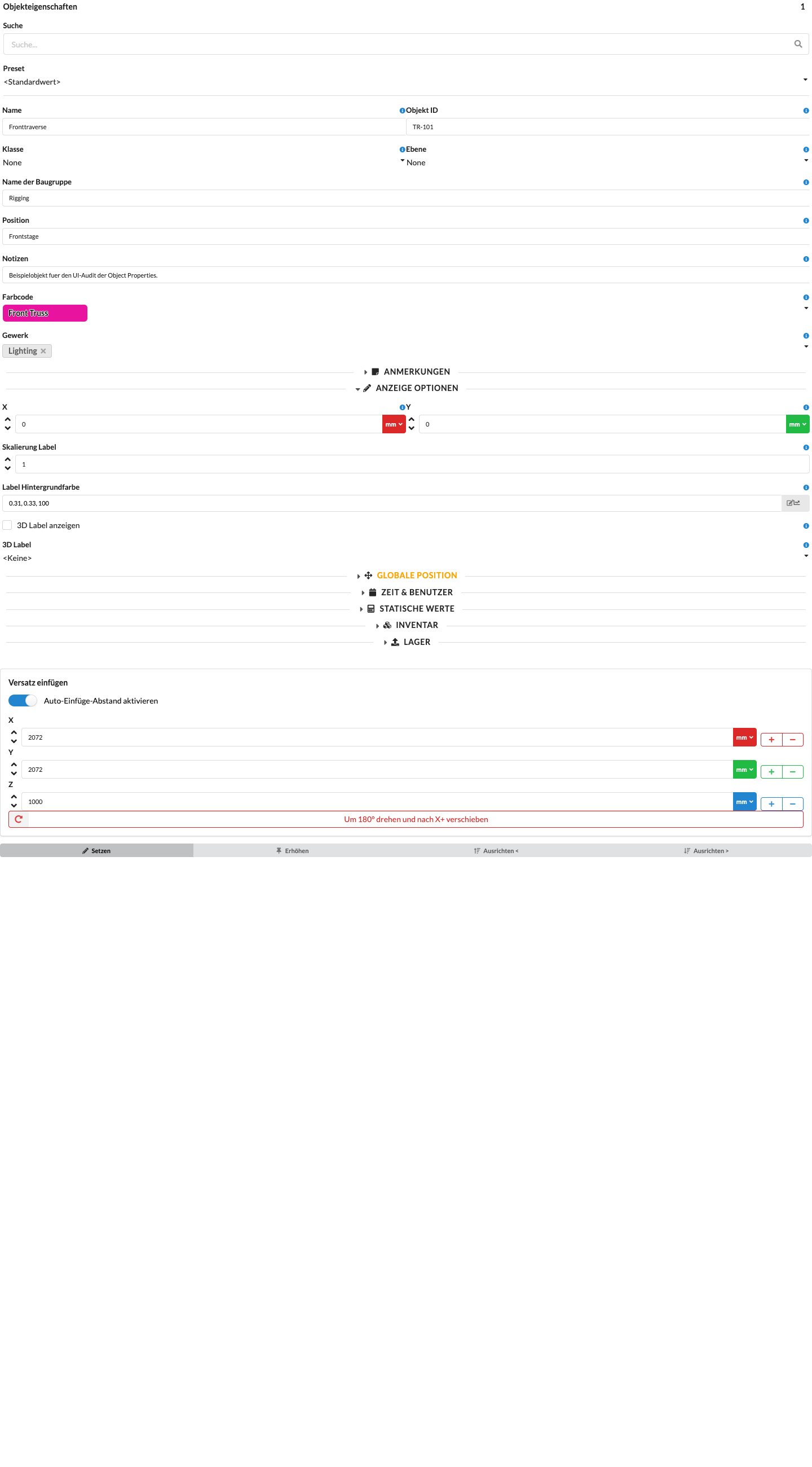
The same colors appear on the position, scale, and rotation fields in Object Properties.
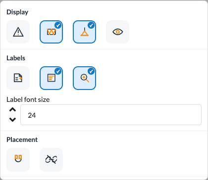
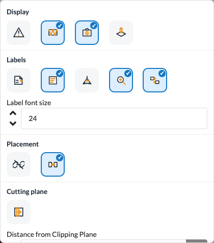
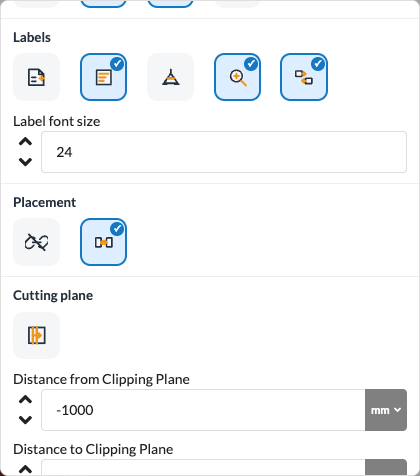
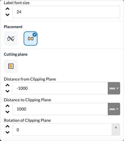
Click the gear icon at the lower left of the 2D or 3D Renderer to open Quick Settings for the current view mode. The larger icons are grouped into Display, Labels, and Placement. In 3D view, the Cutting plane group also contains the section plane switch and fields for start, end, and rotation. Hover over an icon or focus it with the keyboard to see the setting name and description. Click the icon to turn the option on or off. Enabled options are highlighted; changes take effect immediately. In 3D view, options include Perspective Camera View and Enable Section Plane; in 2D view, Show Magnets. There is no gear button in Beam mode. More Renderer settings are in File → Settings... → App → Renderer. Select OK to confirm changes there; Cancel discards them. See the settings overview for descriptions of the options.
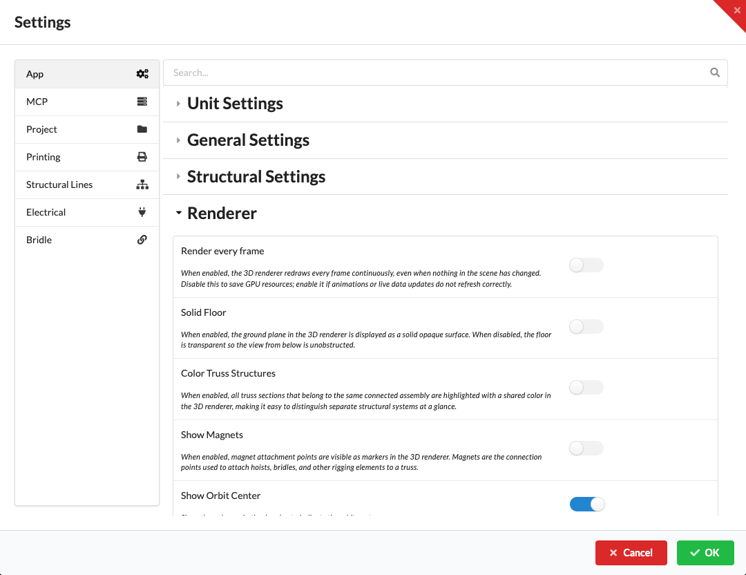
The image shows the top part of the Renderer section; more options are below.
The icon grid includes options for structural errors, automatically generated support labels, and object labels. Hover over an icon or focus it with the keyboard to read its description.
The Show floor support height option displays a horizontal, transparent orange plane with an outline in the 3D view. The plane is at the Floor Level of the Settings profile in the load combination settings. It adapts to the size and position of the drawing and does not clip any model geometry. The display switch is off initially.
If section planes are also enabled, select Start (red), End (green), or Both to edit their handles, or select Floor support height for the floor. The floor plane remains horizontal and cannot be rotated. Unlike the centered on-screen handles for section planes, the floor-height handle is attached directly to the floor plane. It stays connected to it in space while you pan and zoom. If you are looking straight down at the plane, switch to an angled view to move it so the vertical axis is visible. Canceling a drag or switching away from the 3D view discards the unsaved movement.
An error message appears if the floor height cannot be read or saved. If floor settings are unavailable, the Renderer does not show a floor plane and disables the height field. Check the open drawing and the Settings profile in the load combination settings. Hiding the plane changes neither the saved floor height nor Use floor as support.
The existing Quick Settings illustrations show the state before the additional floor-plane icon was added.
Assigned Print Labels, automatically generated support labels, and bridle part names use different display options:
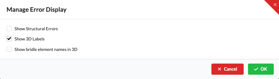
To create printable PDF labels, use File → Export Labels as PDF.... See Export Labels as PDF for the export steps.
Use the section plane to inspect hidden parts and connections in a dense structure. The feature uses two parallel boundaries: a red start plane and a green end plane. In the 3D view, only geometry between these boundaries remains visible. The objects and their model geometry are not changed.
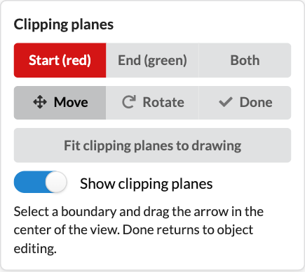
The visible planes adapt to the size and position of the drawing, even far from the coordinate origin. The arrow and ring handles are independent of this: when idle, they are in the center of the visible 3D area and retain their screen size while panning and zooming the view. You do not need to zoom out to reach the handles. This applies to perspective and orthographic cameras.
| Control | Effect |
|---|---|
| Start (red) | Selects the red start boundary to move or use as the center of rotation. |
| End (green) | Selects the green end boundary to move or use as the center of rotation. |
| Both | Selects both boundaries. When moving them, the width of the section range is preserved; when rotating them, the center of rotation is between the planes. |
| Move | Shows the centered arrow for moving the selected boundary or both boundaries. |
| Rotate | Shows the centered ring for rotating the parallel planes together around the vertical Z axis. |
| Done | Ends editing of the section planes and hides the handles. You can select and edit objects again. The section remains active. |
| Fit clipping planes to drawing | Sets both distances so the drawing fits completely within the section range. This replaces the previous section width; the rotation angle is retained. |
| Show clipping planes | Shows or hides the colored planes. Clipping and active handles remain. The application also remembers this display option locally after reloading. |
With Start (red) or End (green), the other boundary stays in place. The boundaries cannot swap places while you drag. For example, use Start and End to set a narrow range around a connection. Then switch to Both to move that same section width farther along the structure.
Select Start (red), End (green), or Both, then select Rotate. Drag the ring in the center of the view and release it at the desired angle. Both planes remain parallel, and their distance from each other stays the same. Rotation is only around the vertical Z axis.
With Start (red) or End (green), the rotation axis runs through the center of the selected plane. With Both, it is halfway between the two planes. The centered on-screen handle shows the control position; it does not mark the plane's position in space.
To get an unobstructed view of the section range you have set:
To make further adjustments, select Move or Rotate. Turn Show clipping planes back on to see the spatial boundaries.
To see the complete drawing without a section again, open the gear icon and turn off Enable Section Plane. Visibility through Layers and Classes in Navigation still applies.
In the gear menu, Distance from the section plane is available for the red start boundary, Distance to the section plane for the green end boundary, and Section plane rotation for their shared angle. Distances can also be negative. They set the position along the section axis; they are not distances from the camera or the centered handles.
You can find the same three values under File → Settings... → App → Renderer. Changes in the gear menu take effect immediately; in the Settings dialog, select OK to confirm or Cancel to discard them. The settings overview explains the options.
| Observation | What to do |
|---|---|
| No expected object is visible after activation. | Select Fit clipping planes to drawing, then gradually narrow the section range. If objects are still missing, check their visibility in Navigation. |
| The arrow or ring is missing. | Check that the 3D view and Enable Section Plane are on. Select Move or Rotate; Done hides the handles. The handles appear in the center of the view, even at high zoom. |
| The colored planes are still visible after Done. | Also turn off Show clipping planes. Done ends handle control and leaves the plane display unchanged. |
| Part of the structure is still missing after hiding the planes. | Show clipping planes controls only the guide display. Turn off Enable Section Plane to disable the section itself. |
For fixtures with GDTF light data, choose the display mode for Spotlight Beam Representations under File → Settings... → App → Renderer. Off is the default and hides the light beam. Fast shows a simplified representation; Beautiful shows a more detailed volumetric representation. The choice affects graphics performance. The older separate switch for a schematic Light Helper is no longer among the available Renderer settings.
This setting affects GDTF light beams in the Renderer, not calculation results.
| Setting | Effect |
|---|---|
| Color Structures | Select this option under File → Settings... → App → Renderer to distinguish connected truss systems by color in the 3D Renderer. Sections of the same structure receive the same color. |
| Show Magnets | Enable this option in the 2D Renderer gear menu or under File → Settings... → App → Renderer to show connection points when inserting and aligning objects. The setting applies to the 2D and 3D Renderer; it does not add connection points to a symbol that has none. |
| Setting | Effect |
|---|---|
| Continuous Rendering | Enable this option under File → Settings... → App → Renderer if animations or live data do not update correctly in the 3D Renderer. The view is then redrawn continuously, even when there are no changes, and uses additional graphics resources. |
| Render Floor Opaque | Enable this option under File → Settings... → App → Renderer to make the ground plane opaque in the 3D Renderer. When disabled, it remains transparent so the view from below is not obscured. |
To inspect the load-bearing lines of an object or internal structural details, open File → Settings... → App → Renderer. Enable Show Structure to display structural geometry in 2D and 3D, and Show Internal Structure to display additional internal details in 3D. Both options are normally off. These details are displayed regardless of the switches when editing a geometry definition.
Use Show Grid to show or hide the orientation grid in the 3D view. The grid is visible by default. Show Ground Supports controls the display of Ground Support geometry in 2D and 3D; it is enabled by default. Hiding a Ground Support does not remove it from the drawing. It may still be visible in edit mode.
When you place an object with the insertion tool, Cancel Insertion appears at the top of the 2D, 3D, or Beam Renderer. Use it to return to simple selection. Objects already placed remain in the drawing. The Toolbar describes the tools and their selection modes.
When you edit an object or symbol definition in the Renderer, the yellow bar shows Close Without Saving and Close and Save. Choose the first button to discard changes from this editing mode, or the second to apply them. See Object-Geometry Relationship for the relationship between object and symbol definitions.
The Resource Manager shows a small 3D preview of the selected geometry, symbol, or fixture. Use it to check a resource before using it in the drawing.
Online changes have a separate 3D comparison view. New objects appear in green, changed objects in blue, and deleted objects in red. The view shows differences between drawing versions; open the drawing itself to edit it.
When editing a label template, the 2D Renderer provides a paper preview and lets you select an object for preview data. The switches and search are described under Designing Labels.
Control the display of moment, shear force, and deflection on calculated structures with Section Reactions in Navigation. Beam View shows the corresponding calculated distributions along a structural beam; they are hidden when there are no calculation results.
Bridles provides one/all-bridle drawings, 3D dimensions, plan/elevation projections, ordered parts lists, automatic population, and drag-and-drop assembly. Edit Bridle… in Object Properties opens this workspace. Part and junction-height edits remain in a preview until Apply changes; Cancel discards the preview. Header dragging saves overview order separately. The detailed guide is available in German.