

In the Errors Navigation tab, Production Assist displays messages generated during the most recent check of the active drawing. Checks run, among other times, after a structural or electrical calculation. Entries are grouped by internal check groups, so a group heading may be more general than the text of an individual entry.
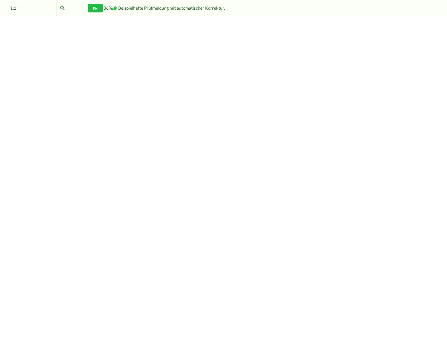
Select the magnifying-glass icon to select the affected object and zoom to the saved error location. Fix applies a predefined correction. Some errors offer a second correction as well. The percentage indicates only the confidence of the automatically suggested target point. Recalculate the drawing after each correction. For general instructions on using the error list, see Errors in Navigation.
The following sections describe all standard messages generated directly by the program. Messages from custom check scripts may also appear under a freely chosen group name.
The BRIDLE_INTERSECTIONS check group, titled Bridle rope collision or insufficient clearance, reports when the axis of a rigged bridle leg or drop intersects the 3D geometry of another object, lies entirely inside a closed mesh, or reaches the configured safety clearance and no suitable rebuild with sufficient clearance can be found. Before reporting the issue, the Material Engine tries another assembly from the available parts. Fixed rope selections, manual parts, and disabled automatic assembly remain binding. The message names the other object and stores an affected position for display in the model. The check runs automatically in the background while Use Bridle Material Engine is enabled, even without live structural calculation.
Select the entry in the error list and inspect the rope path in the 3D model. Correct the bridle geometry or material selection, or move the obstruction. Under File → Settings... → Bridle → Bridle Safety Clearance, check whether the clearance suits the plan: the default is 100 mm from the rope axis to the 3D surface; 0 mm limits the check to actual collisions. Confirm changes with OK. The error entry does not offer an additional Fix. A resolved conflict disappears after the next background check. Objects connected at the start or end of the respective leg are not reported as a collision or clearance conflict, even if the attachment point lies within their 3D geometry. Other obstructions remain part of the check. An object cannot be checked without a 3D mesh; the first and last millimeter of the rope are excluded in each case. Rope diameter is not part of the check. Requirements and further limits are described in Check the Rope Path for Collisions and Safety Clearance.
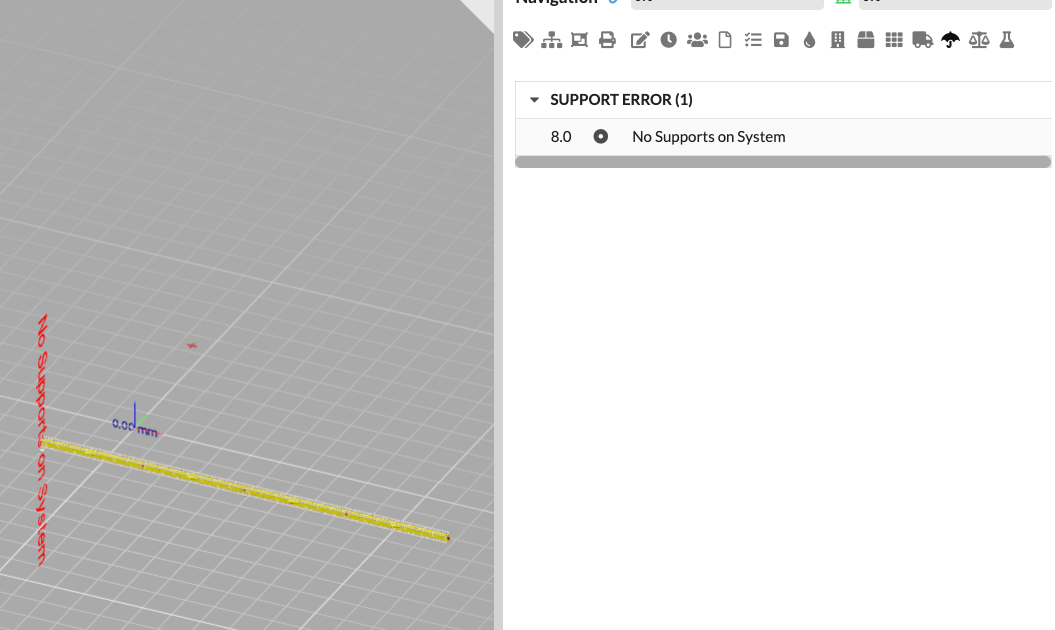
When does this error occur?
The calculation does not detect a support in a connected structural system. The system contains structural elements but no effective support.
Why does this happen?
A support is not on a calculable structural element, is outside the calculation scope, or was not detected when the system was assembled.
How to fix the error:
Add a suitable support or move an existing support onto the structural element. Also check visibility, layers, classes, and the configured calculation scope. The offered Calculate Support Positions correction can place suitable supports automatically. Still check the resulting positions manually.
SUPPORT_ERROR)#When does this error occur?
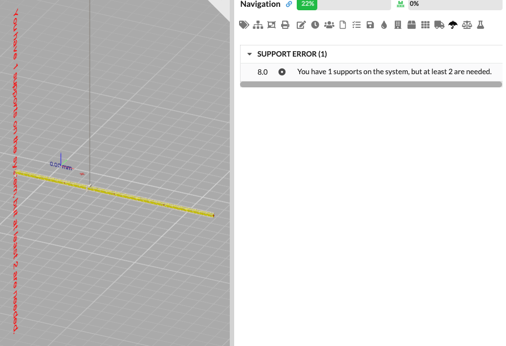
The message includes the detected number and the required minimum, for example You have X supports in the system, but at least Y are required. Depending on the system shape, the code uses different minimum values: a vertical line requires at least one support, a simple horizontal line at least two, a vertical plane at least two, and other systems generally three.
Why does this happen?
Part of the structure is not adequately supported for the calculation. Supports may be missing, outside the structure, or excluded by the calculation scope.
How to fix the error:
Place the missing supports at the intended connection points. If the structure is intentionally supported differently, correct the support connections and properties. The calculation may create additional auxiliary supports internally so that it can continue; these do not replace correctly modeled supports in the plan.
DUPLICATE_SUPPORT_ERROR)#When does this error occur?
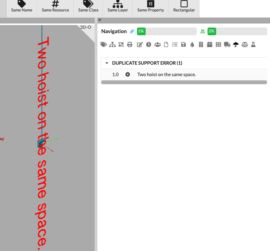
Two supports are detected at the same calculated position.
Why does this happen?
Supports or support geometry overlap. This makes it unclear which support condition actually applies at that point.
How to fix the error:
Select the entry, check the highlighted supports, and move or delete the extra support. Then recalculate.
When does this error occur?
A support is not connected to enough structural members and is also not connected to the system by a load. For a regular lower support, the check detects fewer than two connected frames; for a Ground Support, it detects fewer than one connected structural member.
Why does this happen?
The support is next to the structure, at the wrong height, or modeled as a support even though its associated geometry is not actually in contact. The message can be hidden using the setting for suppressing unconnected supports.
How to fix the error:
Move the support to the intended connection point and check the geometry connection. If the support is intentionally not meant to take part in the calculation, exclude it through the calculation scope or the relevant object options.
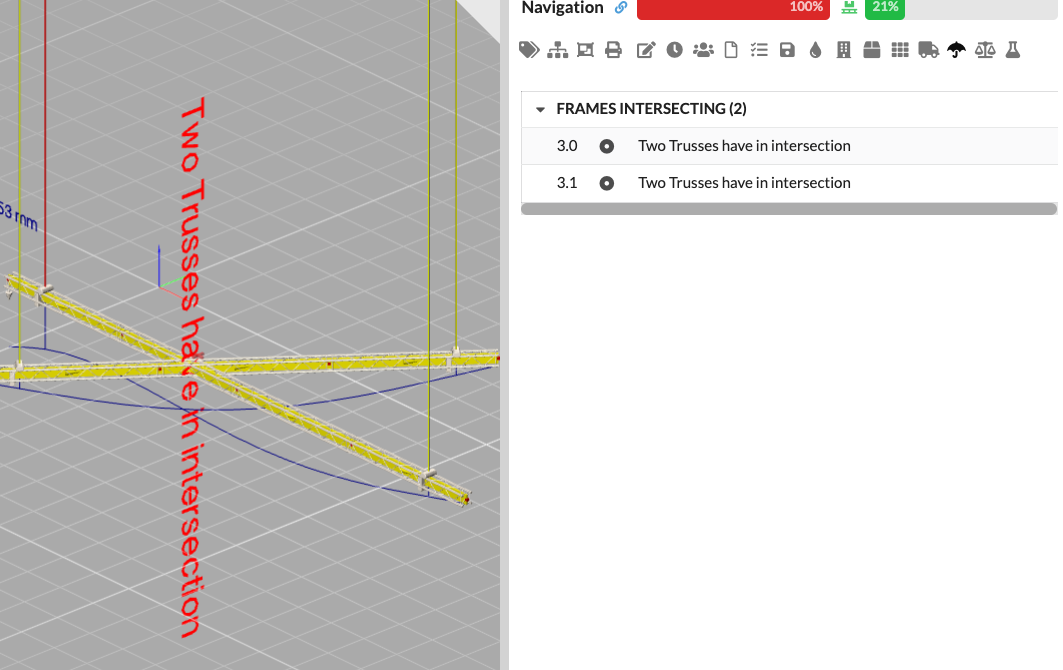
FRAMES_INTERSECTING)#When does this error occur?
Two structural members from different objects geometrically intersect between their endpoints. The check applies to members not marked as a truss crossing and reports the intersection only if the cross section enables this check.
Why does this happen?
The members occupy colliding heights or positions. This assumes a connection at the intersection that may not be intended in the structural model.
How to fix the error:
Check whether the intersection is intentional in the construction. Move or rotate one of the members, correct its height, or explicitly model the intended connection. Then recalculate.
When does this error occur?
The FrameNoCrossSection group contains a message such as [Cross Section] has no valid cross section. It occurs for a regular structural member when the internal cross section in use does not provide valid cross-section data. Eccentric Frames, truss crossings, and the internal Stiff cross section are excluded from this check.
Why does this happen?
The selected cross section is missing, was imported incompletely, or does not match the cross-section and material data required for the calculation.
How to fix the error:
Open the properties of the highlighted structural member and select a valid cross section from the Resource Manager. For custom cross sections, check the dimensions, material, and calculation values. Then run Rigging → Calculate Structural Analysis.
You can also set the cross section directly on the Structure element in the symbol definition: open Edit Mode, select the Structure element in the Scene Tree, and change the cross section in Object Properties. The steps are described under Structure Elements in the Symbol Workflow. If you instead want to enforce a cross section on the whole object for the calculation, use Cross Section Override in the structural properties.
When does this error occur?
The LOAD_ERROR_FRAME group is generated when the self-weight calculated from the cross section of a regular structural member is zero or negative. Cross sections for which the weight warning is intentionally suppressed, as well as Eccentric Frames and truss crossings, are skipped.
Why does this happen?
The cross section has no self-weight, or its material density and cross-sectional area are missing. As a result, the structural member's self-weight cannot be included in the calculation. If the object weight is 0, Production Assist normally uses the self-weight per unit length stored in the cross section as a distributed load instead. In ballast calculation mode, the object weight of Ground Supports is deliberately ignored; in this case, no cross-section distributed load is used as a substitute.
How to fix the error:
Choose a cross section with a valid self-weight and material, or add the missing data to the cross section. Then check that the resulting self-weight matches the actual structure.
When does this error occur?
The CheckNodesToHaveConnectionsErrors group appears at a node that receives a special check because it has hinges on both sides and ends up connected to fewer than two structural members.
Why does this happen?
A hinge interrupts force transfer, or a structural member ends freely even though another connection is required at that node.
How to fix the error:
Check the highlighted node location and the hinges on the adjacent structural members. Connect the node to the intended member, or correct the hinges if they were added by mistake.
When does this error occur?
The SCAFF_CONNECTION_ERROR group is generated for scaffold connections when two connected directions at a shared node are detected as duplicates or conflicting because they are within 30 degrees of each other.
Why does this happen?
Several scaffold members meet at the same connection point with nearly the same direction. This may indicate duplicate members, incorrect alignment, or an invalid connection.
How to fix the error:
Check all highlighted members at the connection. Remove duplicate members, correct their direction, or use the intended connection geometry. This message does not offer an automatic correction.
When does this error occur?
The LOAD_NO_WEIGHT group is generated when an object used as a load has a negative or practically zero weight. Warnings are issued in particular for audio objects, fixtures, and support objects without a Ground Support. The warning for certain supports can be suppressed in the settings.
Why does this happen?
The load object's inventory weight is missing, is zero, or was not taken from the object information. Without a weight, the load cannot be calculated.
How to fix the error:
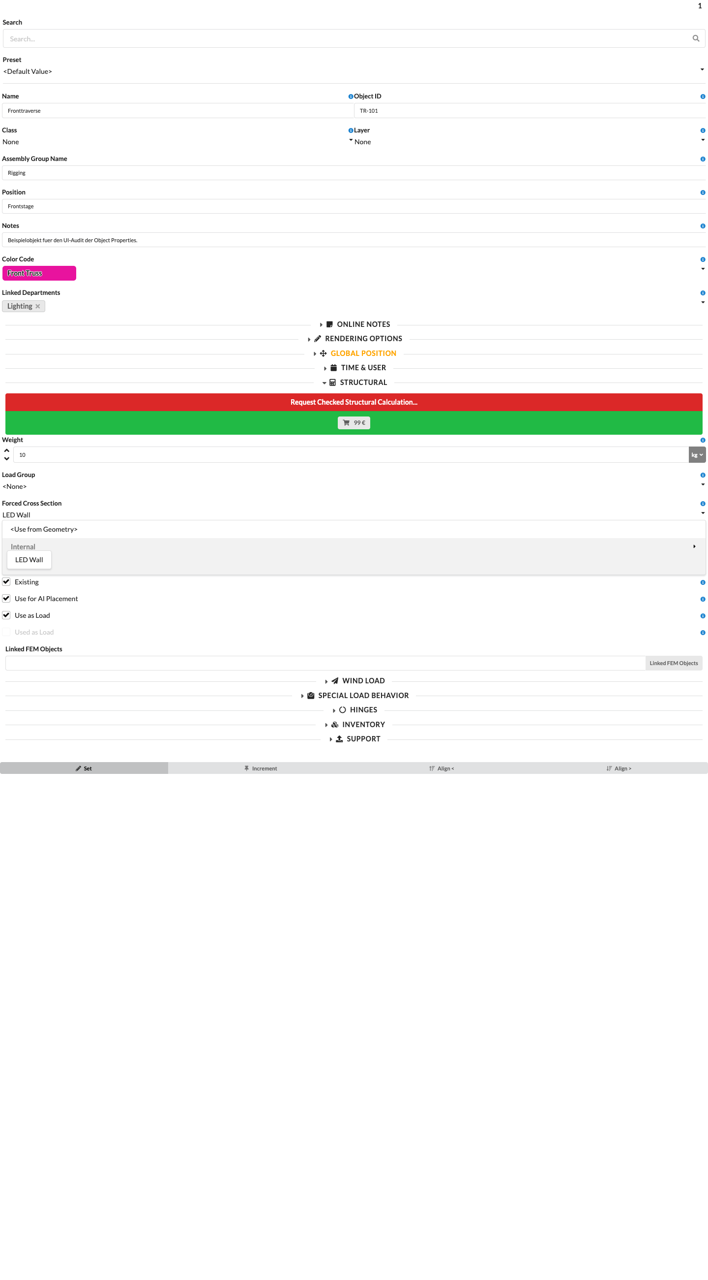
Enter the actual weight under Object Properties → Inventory → Weight. The message offers Set Weight. Details about this correction are provided under Set Weight. For similar objects, check whether only the selected object or other objects should also be adjusted.
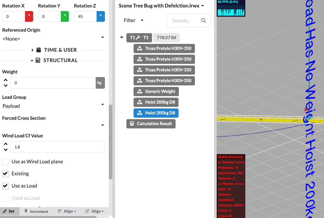
When does this error occur?
The LOAD_ERROR group reports a load object whose path or load point could not be assigned to a calculable structural element, support, or enabled floor surface. For point loads, supports in exact contact are checked first, followed by nearby supports and, optionally, the floor. For load paths, at least one section must lie on a suitable structure.
Why does this happen?
The load point is too far from the structure, the load path contains an uncovered section, or Match Loads to Floor is not enabled for a load at height zero.
How to fix the error:
Move the load point or load path onto the intended structure. The offered correction moves the object to the nearest suitable member; for loads, you can also move only the load point. For floor loads, check the App_MatchLoadsToFloor setting and the height of the load point.
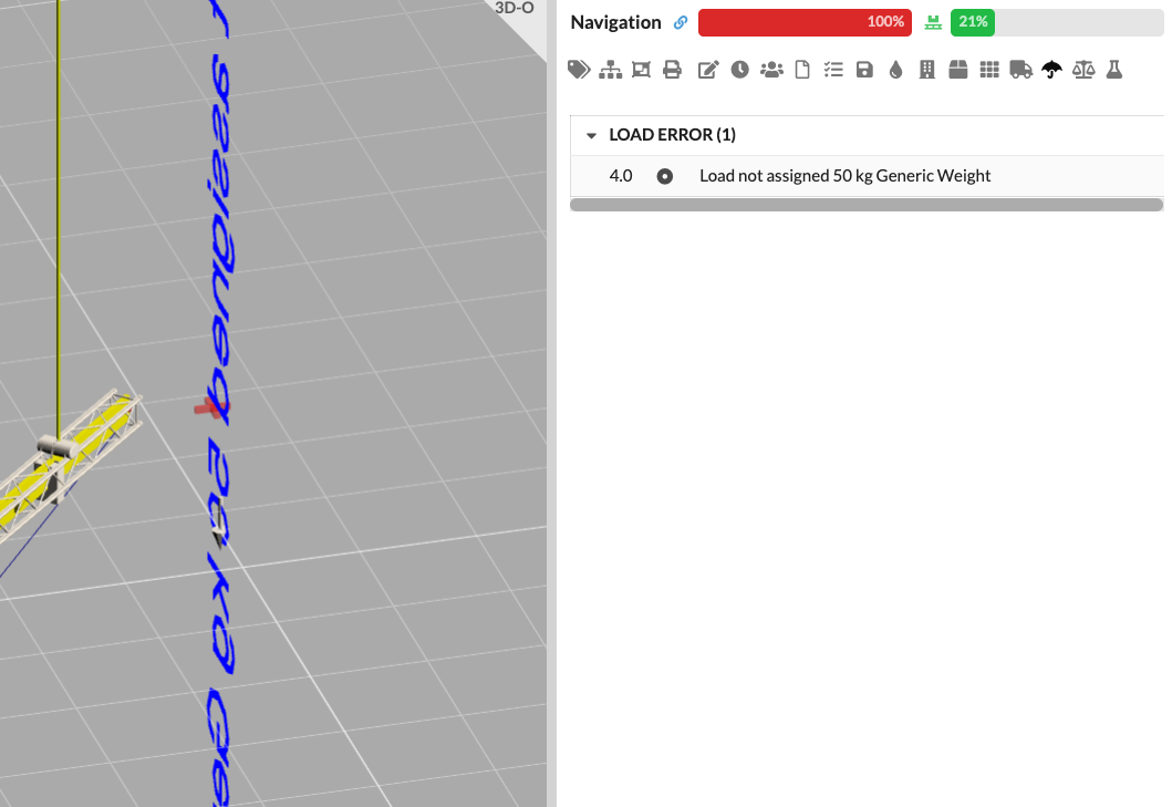
When does this error occur?
For a load path, the length of the assigned structure is compared with the length of the drawn path. The message Too Much Line Load Assigned appears when the assigned length is greater; Too Little Line Load Assigned appears when there is a gap.
Why does this happen?
The load path overlaps structural elements, contains gaps, or runs partly alongside the structure.
How to fix the error:
Check the entire load path, including its start, end, and bends. Remove overlaps, close gaps, and align the path with suitable structural elements. Then recalculate.
When does this error occur?
This message is generated for a load geometry that is not recognized as a line load and cannot be assigned to a frame. The text includes the calculated force and the object name.
Why does this happen?
The point force is outside the permitted distance from a member, or the selected member is not a calculable structural member.
How to fix the error:
Move the point force onto the intended member or adjust the structural assignment. Then check the force direction and magnitude again.
When does this error occur?
This error appears in the LOAD_AREA_ERROR group when an object is used as an Area Load Surface, but its polygon area cannot be successfully transferred to the calculable structure.
Why does this happen?
The area is not on a suitable structure, is interrupted, or its geometry cannot be mapped onto the structural members.
How to fix the error:
Check the polygon and move the area so that it lies completely on the intended structure. Remove invalid or duplicate points, and check the weight and load parameters.
When does this error occur?
This message appears for an object with the Free Load option enabled when its path cannot be assigned to a calculable structure.
Why does this happen?
The free load path lies beside the structure, contains invalid geometry, or does not intersect any suitable structural members.
How to fix the error:
Edit the path until it lies on the intended structure, or disable Free Load if the object should not be calculated as a free load.
When does this error occur?
The DropErrors group reports a drop whose result is not connected to the structure at the upper connection point. The message is generated only when the drop connection check is enabled for the drop geometry.
Why does this happen?
The drop is beside the upper supporting member, or its connection geometry points to a different location.
How to fix the error:
Check the upper drop geometry and move or rotate it to the intended connection point. Then run the calculation again.
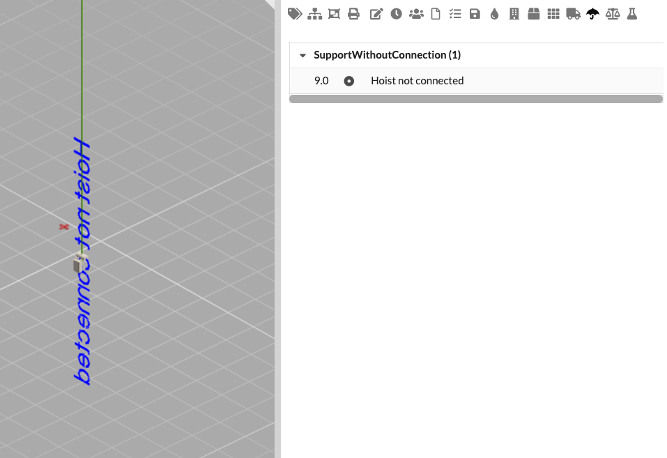
This case is generated in the code as Hoist Not Attached and displayed in the SupportWithoutConnection group. Its cause and solution are the same as for Support Not Connected. If the message is not needed despite the correct position, you can disable the warning using the setting for suppressing unconnected supports.
The message System unstable after rope loss appears in the ROPE_LOSS_INSTABILITY group when one or more ropes or tension-only elements lose their tensile action and the solver then reports an unstable stiffness matrix or a matrix error. The entries mark the affected ropes and name the load combination. A slack rope alone does not trigger this message if the rest of the system can still be calculated stably.
Check the rope geometry, supports, load distribution, and rope settings. Ropes cannot carry compressive forces. If sufficient support is no longer available after a rope fails, the supports or load distribution must be corrected. Then calculate again. Errors from other load combinations remain visible until those combinations have also been recalculated successfully.
The message remains visible when you hide the technical FEM solver diagnostics using Show FEA diagnostics in the app settings for structural calculation. The calculation status message The deflection of the static system is too large is still generated when the FEM solution exceeds the permitted deformation limit.
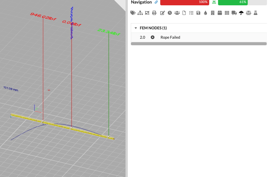
When does this error occur?
The CALC_ERRORS group is generated when second-order calculation is enabled and the calculation reports that it has failed in this state.
Why does this happen?
The system cannot be solved while accounting for second-order effects. Common causes include large deformations, unstable supports, or multiple rope failures.
How to fix the error:
First check the structure, supports, and loads. If second-order effects are not required for this assessment, the entry offers a correction to disable second-order calculation. Then run the calculation again.
When does this error occur?
The FEM_SOLVER_DIAGNOSTICS group contains technical details when the FEM solver reports a matrix error or an unstable stiffness matrix and provides diagnostics. The messages identify the node, degree of freedom, and a diagnostic hint. A maximum of twelve entries is displayed per solver run.
Use Show FEA diagnostics under Settings > App > Structural Calculation Settings to show or hide these details in the error list and drawing. The setting is enabled by default. Hiding the details does not change the calculation or suppress actual structural errors. Saved diagnostics are displayed again when you enable the setting.
Why does this happen?
Typical diagnostic hints include an unsupported or unconnected degree of freedom, a non-finite diagonal, a diagonal close to zero, or a negative diagonal. If the solver cannot directly assign the cause, it displays the smallest diagonal entries as clues. This list does not necessarily identify the actual failure locations.
How to fix the error:
At the marked node, check the connections, supports, hinges, and cross section used. Remove free or duplicate geometry and make sure every required degree of freedom is restrained by the structure or supports. If the cause remains unclear after these checks, contact Production Assist Support and provide the diagnostic message.
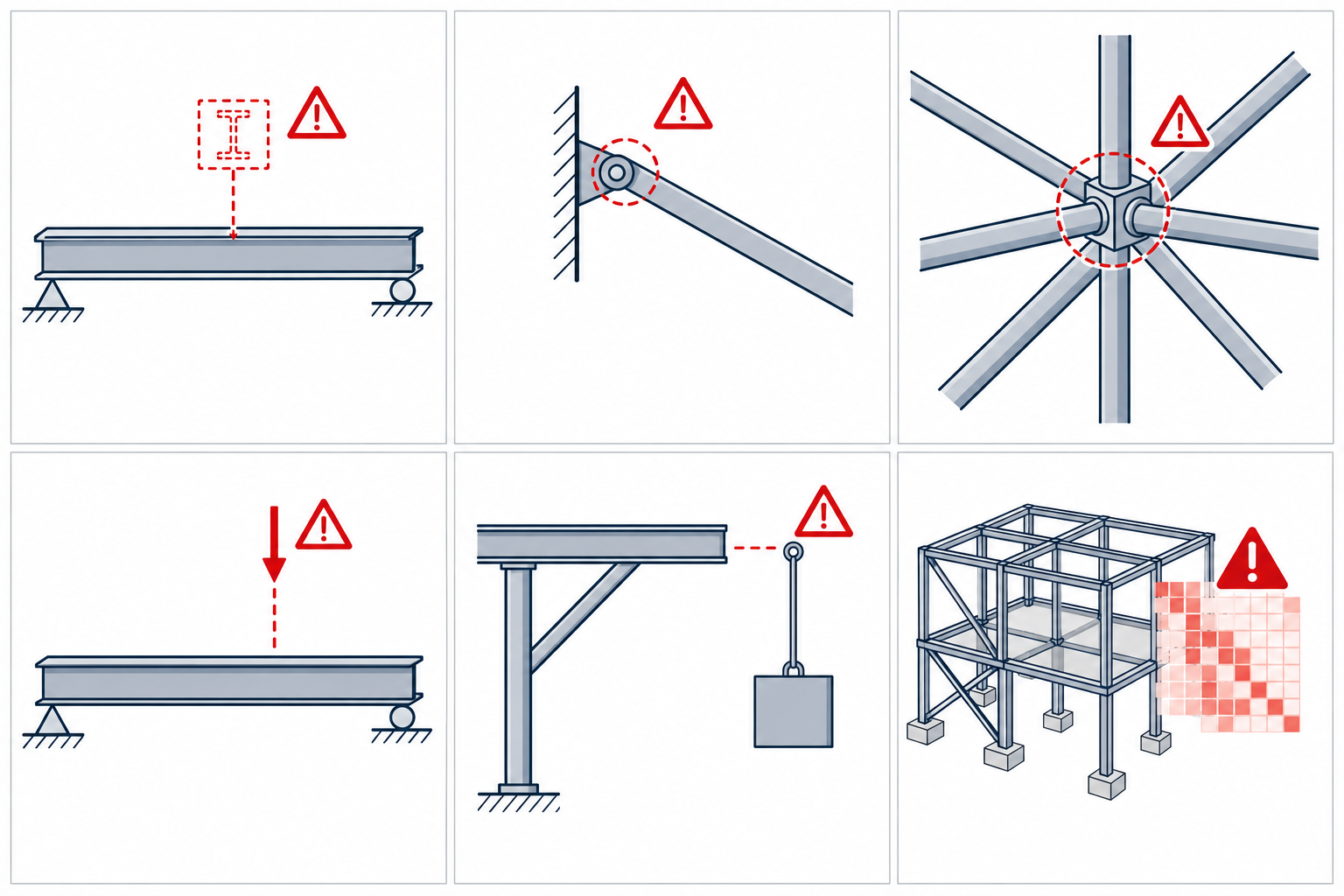
The FEM_NODES group contains two types of automatically generated entries:
At the highlighted point, check the supports, hinges, and member connections. Add the missing restraint or correct the model. The check identifies the affected degrees of freedom but does not provide an automatic correction.
When does this error occur?
The OUT_USED_TWO_TIMES group is generated when an output has more than one connection. This also applies to network outputs that are carried forward more than once in the data calculation.
Why does this happen?
An output is connected to multiple inputs or consumers, even though the output in use expects a single connection.
How to fix the error:
Open Window → Wiring, select the reported output, and remove the unintended connection. If multiple consumers need to be supplied, use the intended distribution or wiring structure. See Electrical View for instructions.
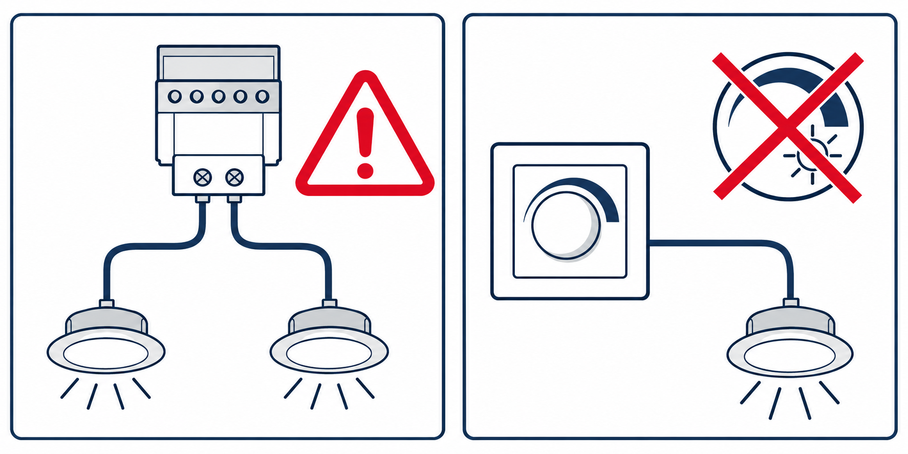
When does this error occur?
The DIMMER_ERROR group is generated when a consumer is connected to a dimmer and its Consumer is dimmable property is not enabled.
Why does this happen?
According to its object information, the connected device does not support dimming but receives a dimmer signal.
How to fix the error:
Check the device's technical specifications. Enable Consumer is dimmable only if the device is actually dimmable. Otherwise, connect it to a suitable non-dimmable output.
Not every entry returned by LR_GetDrawingErrors is an error. The following groups are also generated automatically, so they appear in the same error list or in the renderer.
The DisplayLoadErrors group does not contain an error message. When Point Load or Line Load is enabled in the renderer settings, the program creates a label for each corresponding load with the effective force and moment values. Use this display to check where the load is applied in the calculation. The labels are removed when both settings are turned off.
The AutoGeneratedGroundSupportResults group contains labels for automatically generated Ground Supports. The entry shows the calculated reaction forces and is marked in the data model as not intended for the list; however, the current error-list component does not reliably filter this field, so the group may still appear there. The label may be visible in the renderer. Its color follows the configured utilization display. Such a label is not an error; if the values look unusual, check the floor load, friction, and Ground Support settings.
The ReplacementMessages group contains suggestions such as Replace [Cross Section] → [Replacement Cross Section]. It is generated for overloaded truss cross sections and offers the Override Cross Section correction. Before applying it, check whether the suggested cross section matches the actual structure. The suggestion is a technical aid, not an automatically approved structural verification.
The integrated calculation does not replace a reviewed structural analysis. For a safety-critical structure, its modeling assumptions, input data, and results must be checked by a qualified person.