

The Scene Tree shows objects in the active drawing as a hierarchical tree. You can select, rename, sort, and filter objects there, and organize the object structure with groups and drag-and-drop. Sorting changes only the visible order; it does not change the object structure or calculation results. For automatic patching, the Patch Tool Order setting can use either the order in the hierarchical Scene Tree or the position on the structure. This setting is independent of the display sorting.
The File → Settings... → General Settings → Automatically group objects in assembly groups setting is enabled by default. When enabled, Production Assist automatically assigns objects that belong to connected structures to suitable Assembly Groups. You can enable or disable this setting in General Settings.
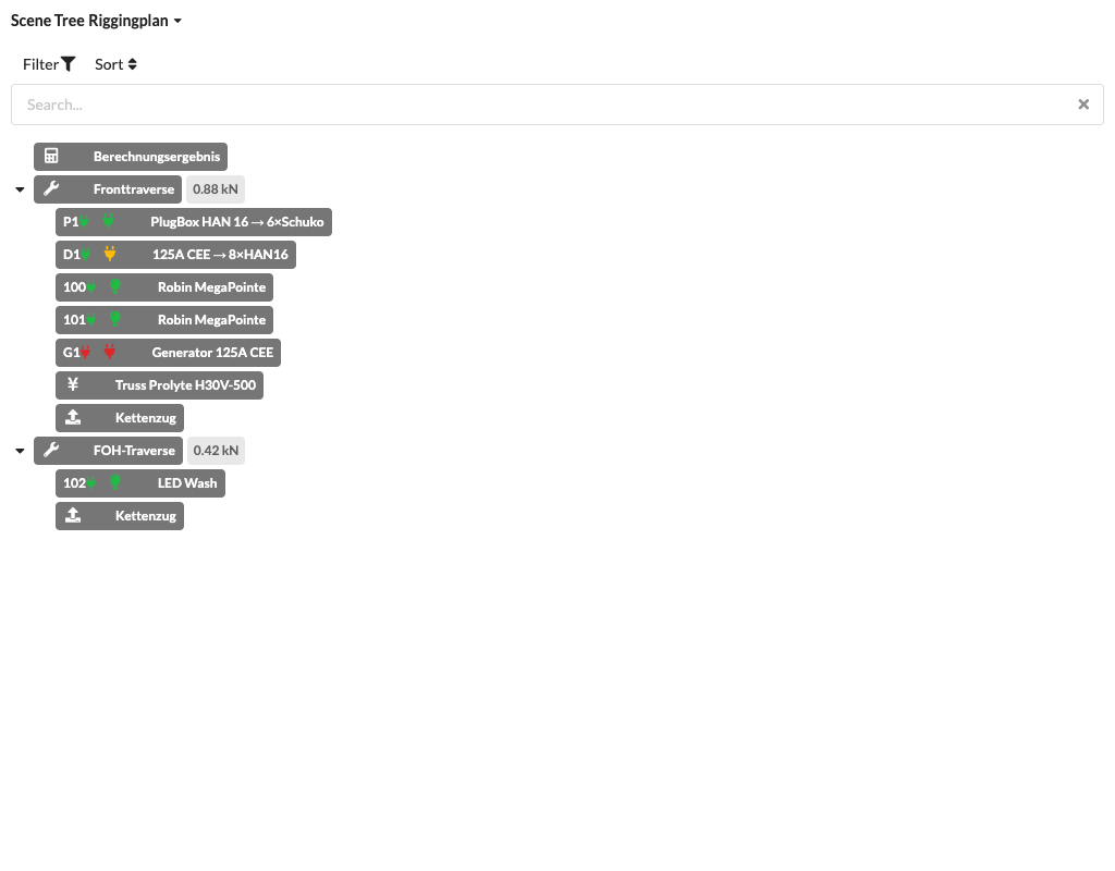
| Control | Effect |
|---|---|
| Drawing name and arrow | Open the list of other open drawings, if the workspace allows switching. |
| Red, blinking Reset calculation scope button | Appears above the tree when a fixed calculation scope is set. Resets the fixed scope and clears the current object selection. |
| Filter | Limits the visible objects according to the selected criteria. |
| Sort | Changes the displayed order without changing the object hierarchy. |
| Search and clear icon | Search for objects and clear the search field. |
| Triangle before an Assembly Group | Expands or collapses its child objects. |
| Object row | Selects the object; its properties appear in Object Properties. |
Next to Structure, Production Assist shows the name of the active drawing. Use the adjacent drop-down menu to switch to another open drawing.
Switching is disabled in Vectorworks. In embedded desktop views, it is available only when the local view is active.
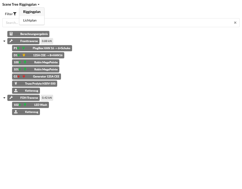
Select the drawing you want to display from the drop-down menu. In the example, Rigging Plan is the active drawing and Lighting Plan is another open drawing.
Click an object row to select it. Hold Cmd on macOS or Ctrl on Windows to add individual objects to the selection or remove them from it.
Use Shift to select a consecutive range: click the first object, then click the last object while holding Shift. The objects between them are selected as well. Double-click an object row to edit its name. Confirm the entry with Enter or click outside the field.
Depending on the object type, object rows in the Scene Tree show additional information directly, for example:
You can combine related objects, such as fixtures on a truss, into an Assembly Group. This improves clarity and helps with tasks such as creating Assembly Sheets. All included objects can be selected and edited together.
The image at the beginning of this chapter shows two expanded Assembly Groups with example objects. The load values and connection statuses in the image are synthetic example data.
To group selected objects into an Assembly Group, select at least two objects. Right-click to open the context menu and choose Group Selected Objects into Assembly Group. Alternatively, use Cmd + G (macOS) or Ctrl + G (Windows). In the Create Assembly Group dialog, the Assembly Group Name field is prefilled with Group. Enter a non-empty name that differs from existing Assembly Group names, ignoring leading and trailing spaces and capitalization, then confirm with OK. The new Assembly Group and the selected objects then appear in the Scene Tree. The dialog fields and name validation are described in the context menu section.
You can nest Assembly Groups. Drag an object or selection onto the desired group. Drop it on the middle of the row to make it a child of that group. Drop it on the top or bottom edge to change its position in the hierarchy. Hold Alt when dropping if you do not want to preserve the global position. Alternatively, use the Move to Assembly Group context menu command for a selection. The steps and prerequisites explain how to select the destination in the dialog.
Changes to the object hierarchy can be undone and redone. This also restores the original position within an Assembly Group or at the top level. The Bridle View uses the same normal object order. An active sort of the Scene Tree display may differ from it; No Sorting shows the saved hierarchy.
NOTE: Some commands also refer to the child objects of an Assembly Group as Child or Children. The parent Assembly Group is called Parent.
You can sort object rows by Name, FID, Position on Structure, Object ID, or an available object property. Open Sort and choose a property. Use Reverse Order to reverse the sorting. To clear the sorting, select No Sorting or click X in the Sorted by... notice.
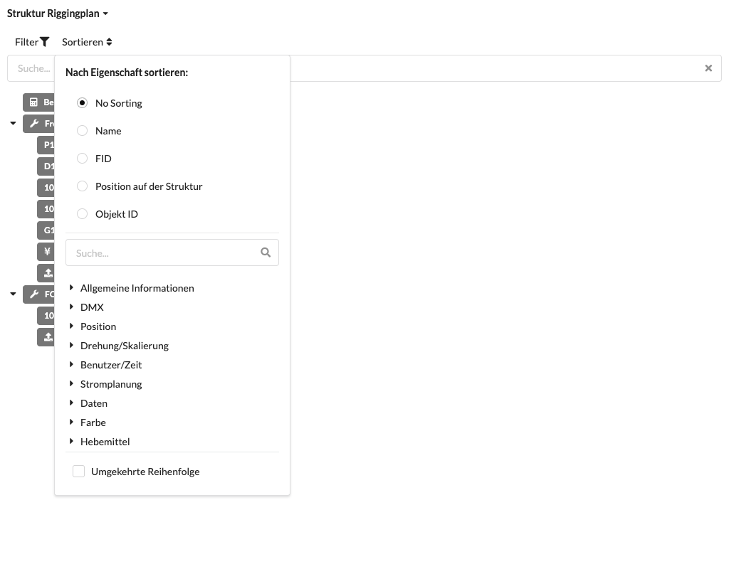
When sorting is active, the Sorted by... notice appears at the top of the Scene Tree. Use the arrows to change the direction and X to clear the sorting. For many properties, the sort value appears next to the object row. For example, sort by Fixture ID to display fixtures in ascending or descending ID order.
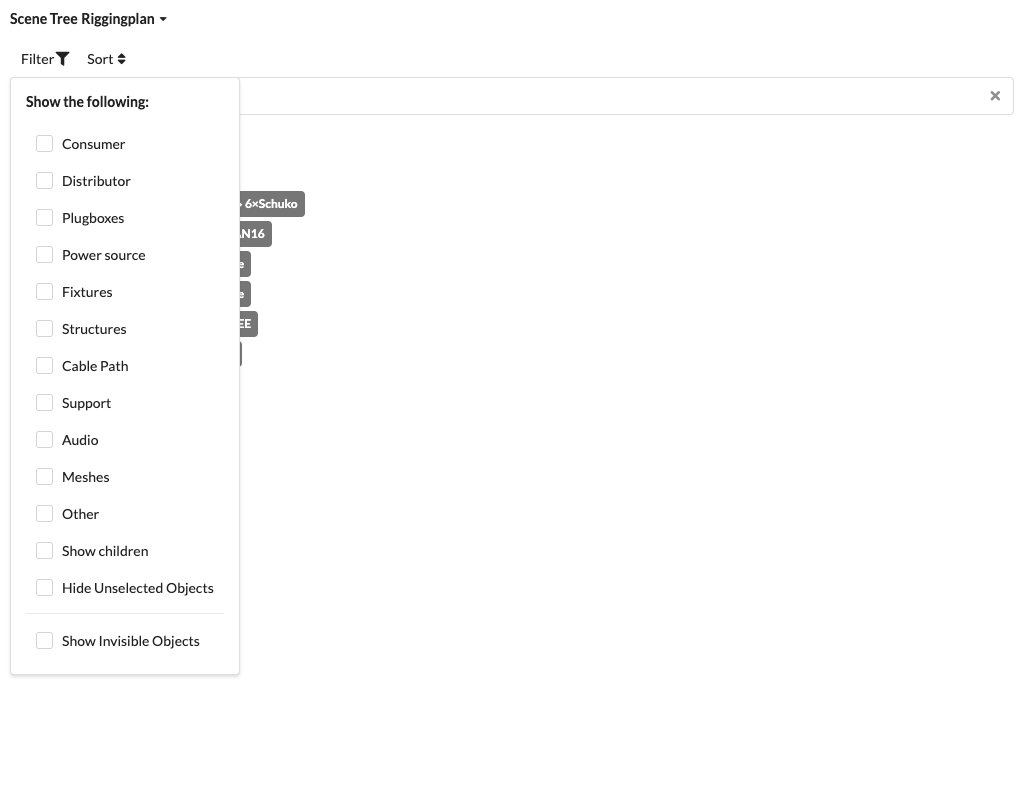
Use Filter to show or hide particular object types. You can also account for selection and visibility, and show the child objects of a matching object when searching.
Enter a name or Object ID in the search field. The search is case-insensitive. You can also search directly for a UUID prefix in curly braces. Click X in the search field to clear the search text.
In the Display: filter menu, use the checked categories to choose which object types are shown. The categories are combined: an object appears if it matches at least one active category. The object type selection applies to the active drawing. All categories are initially enabled in a new drawing. For a focused search, turn off categories that do not match.
The object type filters are combined: an object is shown if it belongs to at least one selected category. Hold Alt and enable a category to turn off all the other categories. Show Sub-Objects and Hide Unselected Objects apply in addition to the object type filters. These two options are reset when the Scene Tree is refreshed.
The icon indicates the object type. Examples:
| Symbol | Object |
|---|---|
| Light bulb | Fixture |
| Tool | Assembly Group |
| Calculator | Calculation result |
| Cube | Mesh geometry |
| Boxes | Symbol definition |
| Tag | Dimension |
The object type icon is followed by a compact, fixed-width marker area styled like the Electron menu icons: Structure (blue), Bridle (orange), and Ground Support (green). The area has the same width in every row so that object names are aligned. Hover over a marker to see a description.
The assigned Object ID or Fixture ID is also displayed before many objects. If the ID is red, it is duplicated in the plan.
For objects with electrical connections, the color of the object icon indicates the connection status:
Note: Right-click an object to open its context menu. For an overview of the commands, see Context Menu.
Note: You can edit symbol and geometry objects in Edit Mode in the Edit Geometry window. See the Symbol Workflow for more steps.