

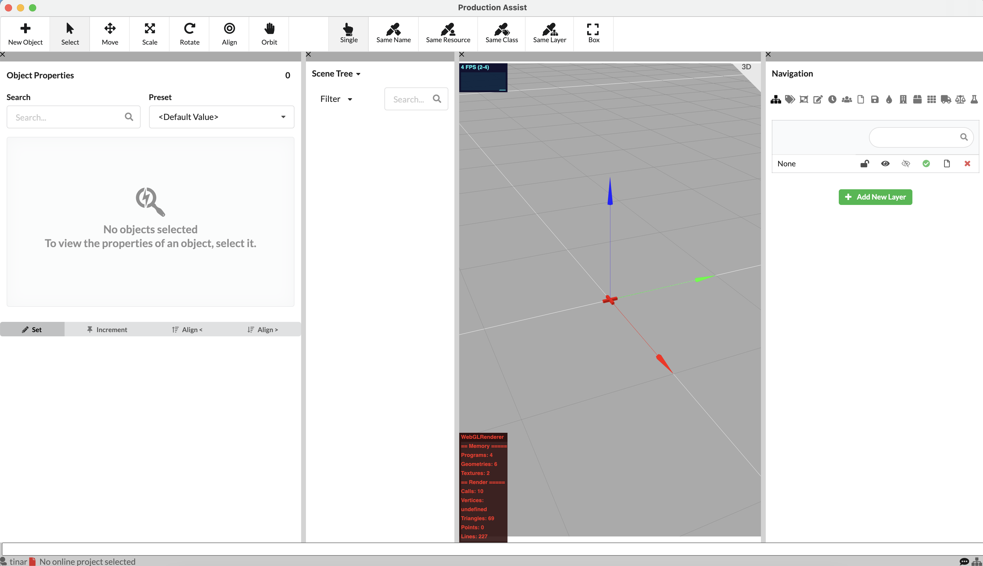
A brief overview of the different areas and what can be found there is summarized in the User Interface chapter.
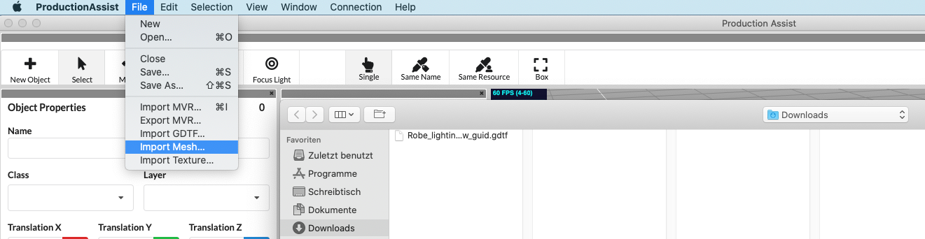
After starting Production Assist, a new empty drawing is available. You have the option to import existing floor plans or 3D geometries. Go to File in the Menubar and select Import PDF, Import 2D Plan, Import Mesh, or Import MVR.
Detailed information on creating a plan with MVR can also be found in the Quick Start Production Assist with MVR Import.
Using the button  in the Toolbar, you can insert all possible objects into the drawing.
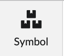
Objects such as trusses, power distributors, chain hoists, or video objects can be found under the SYMBOL button.
The resource selection opens. There you will find all objects from your drawing, from the Production Assist Library, and from your own user library.

Select the desired object and press the gray Import button next to it. The cursor jumps back to the Renderer and marks the insertion point yellow. By clicking the mouse, you can now place your object at the desired location. Further clicking inserts more objects with the same properties. To release the object from the mouse, press the "X" key and you can then select and insert other objects in the same way.
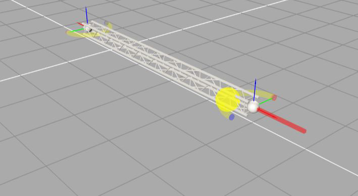
For trusses, there are yellow magnets at the start and end points. These allow easy docking of trusses and thus enable quick assembly of truss lines or more complex structures.
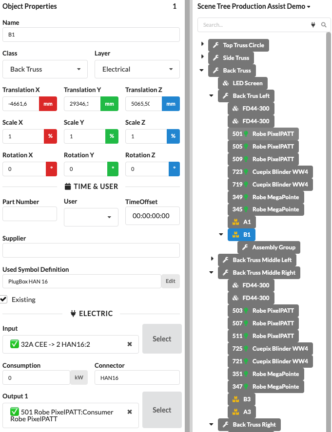
By clicking on the inserted object, you can adjust the Object Properties in the corresponding palette as desired, e.g., name, position, but also electrical connections or object specifications.
By pressing the mouse wheel, you can zoom in and out of objects. You will also find tools in the Toolbar to rotate, scale, mirror, and move objects.
The GDTF (General Device Type Format) is a comprehensive format that contains all the information required to describe a fixture or other device.
Inserting GDTFs can be done in two different ways. To import a GDTF file into a drawing or project, you can select the Import GDTF option under File in the Menubar. A window opens that allows you to import a GDTF file from your local resources.
It is also possible to insert GDTFs by using the New Object tool.
All imported or used fixtures, projectors, or speakers in the drawing are stored as symbols in the Resource Manager. They can be called up there at any time and inserted into the drawing.
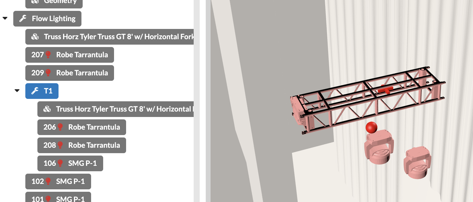
The Scene Tree shows all objects in your drawing and possibly their relationships, for example, which objects are located on the same truss/lighting position. Currently, it is not possible to transfer structures already made in drawings via MVR exchange. Therefore, you must restore them in order to continue working productively with Production Assist. You create so-called Assembly Groups for related objects.
If you already have a good structure defined by layers or classes, it can be very helpful to first group all objects in the Scene Tree accordingly. To do this, click on Edit in the Menubar and then on Group by Class or Group by Layer.
Now you already have grouped objects that belong to the venue or set. If you now want to create individual trusses and their fixtures as an assembly group (Assembly Group), you have several options:
By holding down the SHIFT key, you can select multiple objects one below the other, and by holding down the CMD/CTRL key, multiple separate objects.
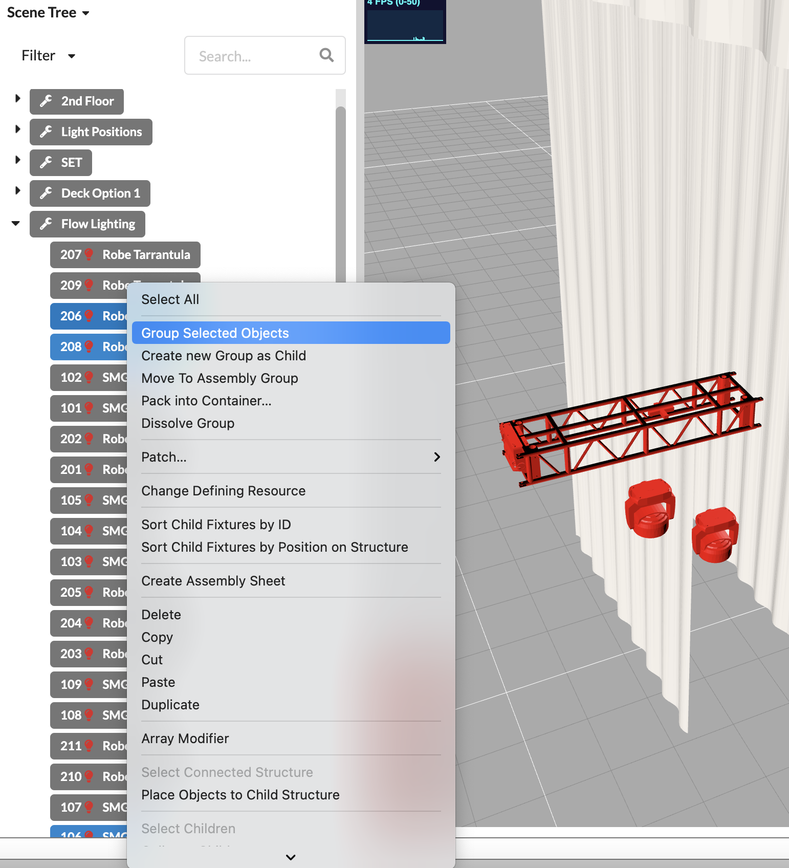
By holding down the SHIFT key, you can select multiple objects one below the other, and by holding down the CMD/CTRL key, multiple separate objects. Or you can use the Box selection variant in the Toolbar.
Now you can create an Assembly Group for all your assembly groups/areas and arrange them by drag and drop in the Scene Tree or push forgotten objects into them.
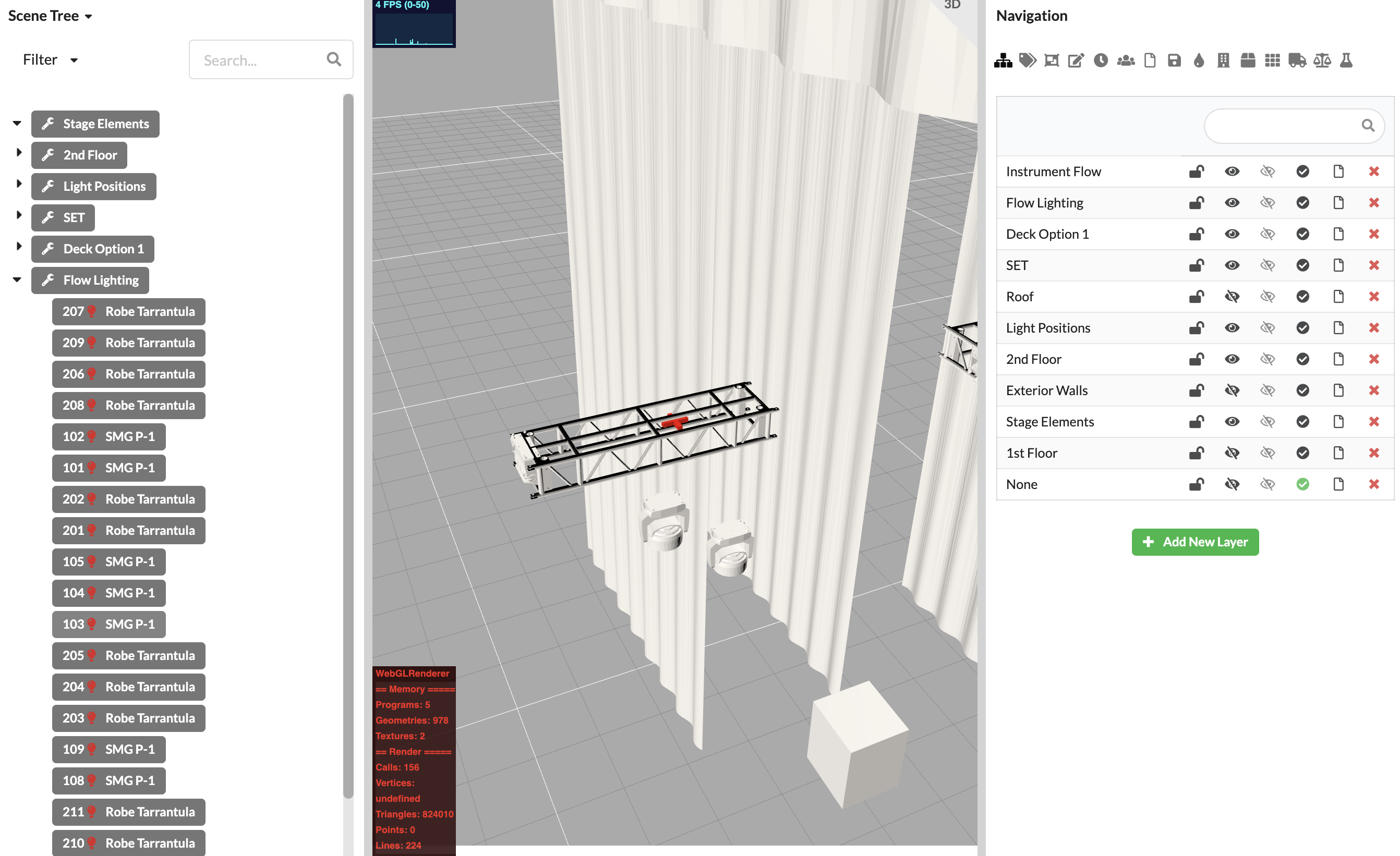
When creating Assembly Groups, it can also be very helpful to use the filter in the Scene Tree to display only certain object types. Or you can control the visibility of objects via Layers and Classes in the Navigation.
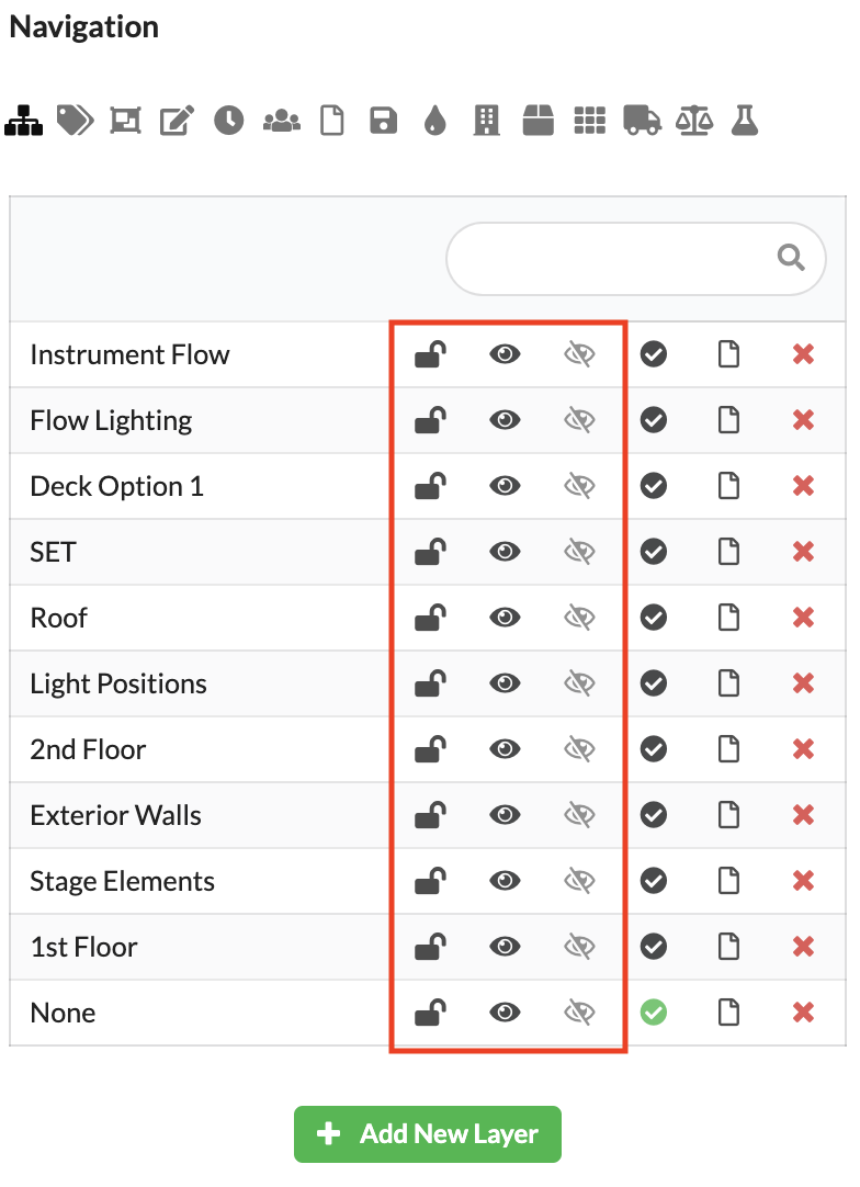
With the lock, you lock and unlock the layer or class. Objects on locked layers or classes cannot be moved, activated, edited, or changed in presets. With the black eye, you control whether objects on this layer/class are visible or invisible. Invisible objects cannot be selected and are not displayed in the Scene Tree or Renderer. If you activate the gray eye for one or more layers/classes, only objects located on that layer/class are visible. All other objects become invisible, regardless of their black eye setting.
If you have structured your Scene Tree well, you now have various options to continue working.
Create power and network patch documentation.