

In Production Assist, you can wire all electrical objects together, view electrical circuit diagrams, view phase loads, and determine power requirements.
We distinguish between three different electrical devices. They are automatically categorized by the electrical connections that their symbol contains.
You can find out more about building symbols here.
If you want to cable your system, you need all the necessary devices in your drawing, i.e., both a power source and all distributors in between. You can then patch all devices either manually or automatically.
There are two ways to connect devices to distributors:
Assignment via device
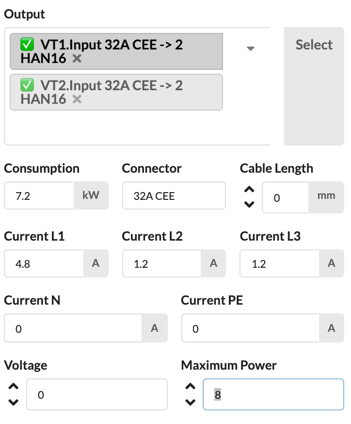
Activate the device, e.g., the spotlight you want to patch. Now open the area Electric & Data in the Object Properties via drop-down menu. You will find the field IN for the power input. Click the box to select the appropriate distributor and slot (socket) from a drop-down menu. The slot is separated from the name of the distributor with a ".". You can also enter the name of a specific distributor in the field so that only its slots are displayed.
A green check mark in front of the name indicates that this port is already occupied. If it is still selected, a query appears as to whether the existing connection should be replaced.

If you have selected a distributor connection and click on the Select button next to it, you will automatically jump to the corresponding distributor symbol and can now continue patching directly there.
Assignment via Plugbox.
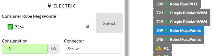
Activate the distributor to which you want to assign the device, e.g., a spotlight. Now open the area Electric & Data in the Object Properties via drop-down menu. You will find its outputs there. Click on the field next to the corresponding output number to select the desired device from a drop-down menu. You can also enter the name or fixture ID of the desired device in the field to find it faster.
A green check mark in front of the name indicates that this port is already occupied. If it is still selected, a query appears as to whether the existing connection should be replaced.
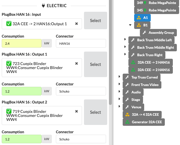
If you have selected a device connection and click on the Select button next to it, you will automatically jump to the corresponding device and can now continue working directly there.
There are also two different options for automatic patching:
Power Patch Children (command in the context menu)
Fixtures or other current drawing objects (consumers) can be automatically connected to a power distributor (distributor) with this command. To do this, both the Consumer and the Distributor must belong to an Assembly Group. Then the Assembly Group can be selected and the command executed. The program automatically searches for the next suitable distributor and connects it to the consumers.
Power Patch Selected Objects (command in the context menu and on the menu bar under Selection)
Select the desired fixtures or other current drawing objects (consumers), as well as the distributors (distributors) to which they should be connected. Production Assist then connects the objects to the selected distributor in sequence.
NOTE: In the app's Settings, you can specify that power patching only connects devices that are in the same Assembly Group. This means that if you have activated e.g., several spotlights and plugboxes from different Assembly Groups, the plugbox will only be connected to spotlights in your Assembly Group. To do this, activate the switch Patch Options only for Local Groups in the Settings.
NOTE: If you want to quickly undo the electrical cabling, you can do so in the menu bar under Selection with the command Delete Power Patch. Before doing so, you must activate the objects to be affected.
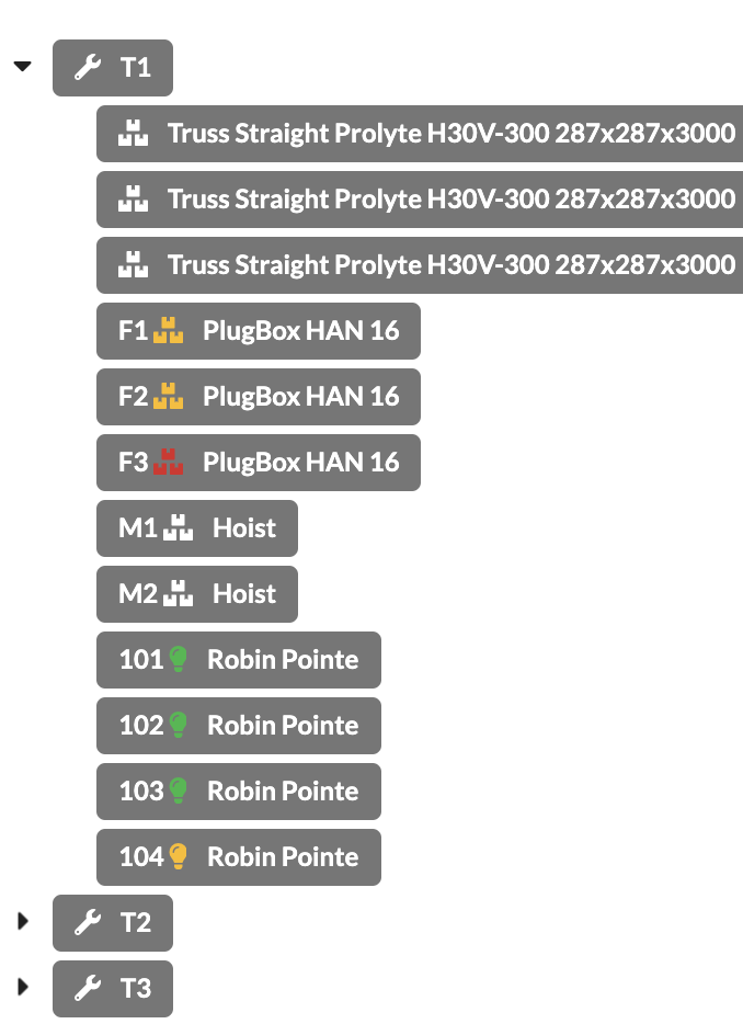
You can easily see in the Scene Tree whether all connections of a device are wired/in use because the symbols before the names of all objects with electrical or network-based connections such as fixtures, power connections, power distributors, consoles, etc. change color in accordance with their status:
TODO: duplicate, object properties from line 90
The color of the Consumption field indicates how heavily the connection is loaded. If the consumption is not overloaded, it will be displayed in green. If there is an overload, this line is displayed in red .
The basis for this is that all consumers as well as all distributors and power sources have stored the correct consumption values ( Consumption ) and load values ( Max Power ) in the symbol or the object properties .
You can also view the phase or system utilization in the Electrical Network overview.
The Electrical Network Window shows the complete power wiring from the generator to each individual device.
You can find it in the menu bar under Window .
There are two different views.
In the repatching window you can see the schematic power wiring as a tree - from the generator to the end device. All devices are displayed with their name, ObjectID, inputs and outputs, as well as the phase loads. Objects that have not yet been wired are listed to the right of the window.
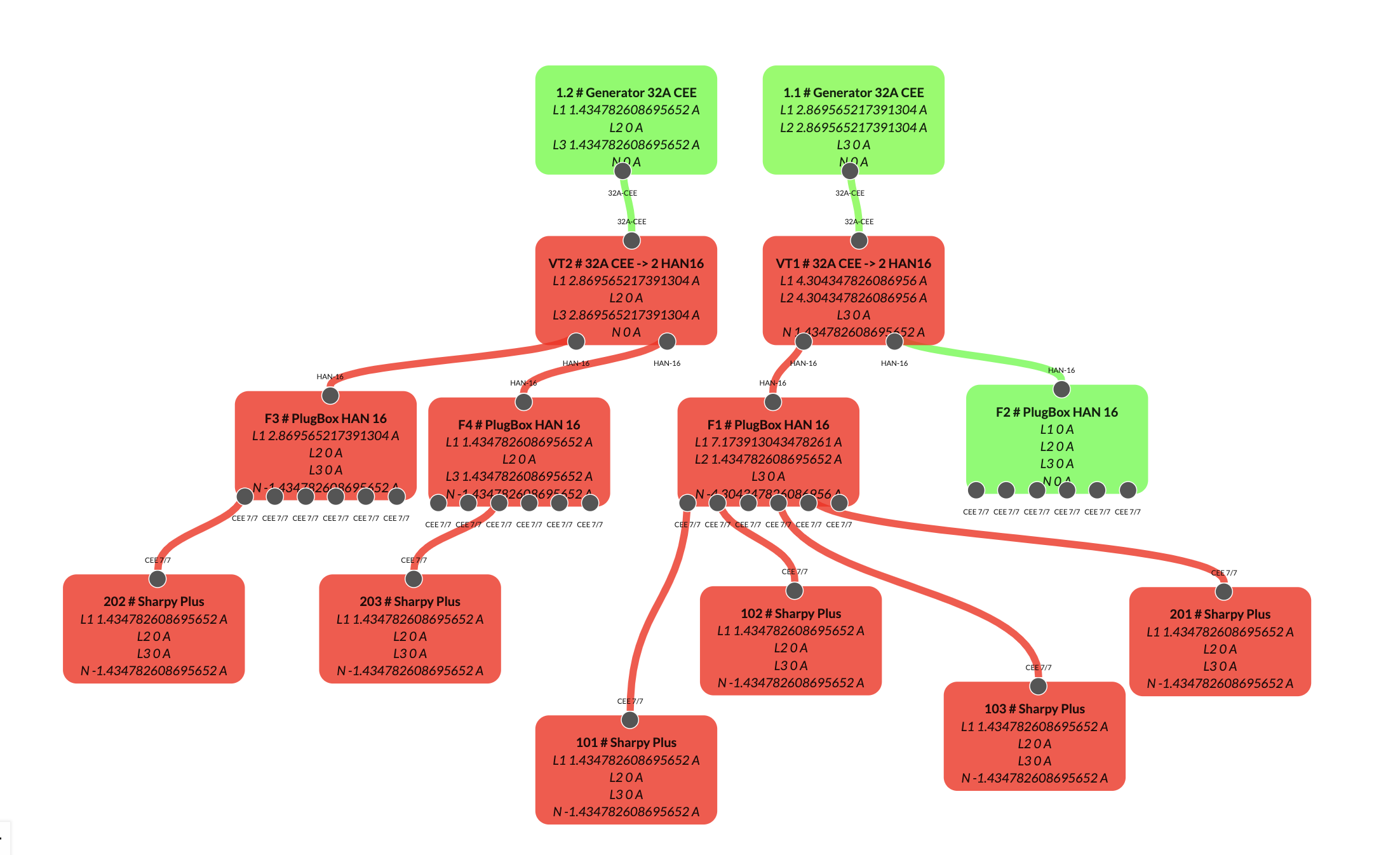
You have the option of moving the position of the individual objects in the repatching window using drag & drop. You can also change the connection between the objects by first clicking on an input and then on an output. If another connection already existed there, you will be asked whether you want to overwrite it.
The colors of the objects show how the load distribution is. If they are green, everything is fine. If they turn red, there is an overload.
You can either move around in the window with the mouse or use the zoom buttons at the bottom left. You can also turn off the editing function by closing the lock.
In the Complete Overview tab you will also find an overview of the power cabling of your system, but this is only a view and cannot be edited. It also shows the internal wiring of the devices between their input and their outputs, as well as the phase utilization there.
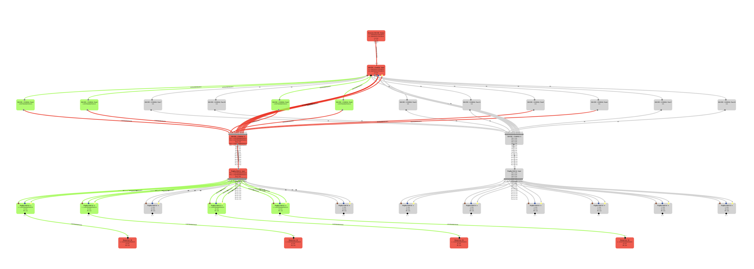
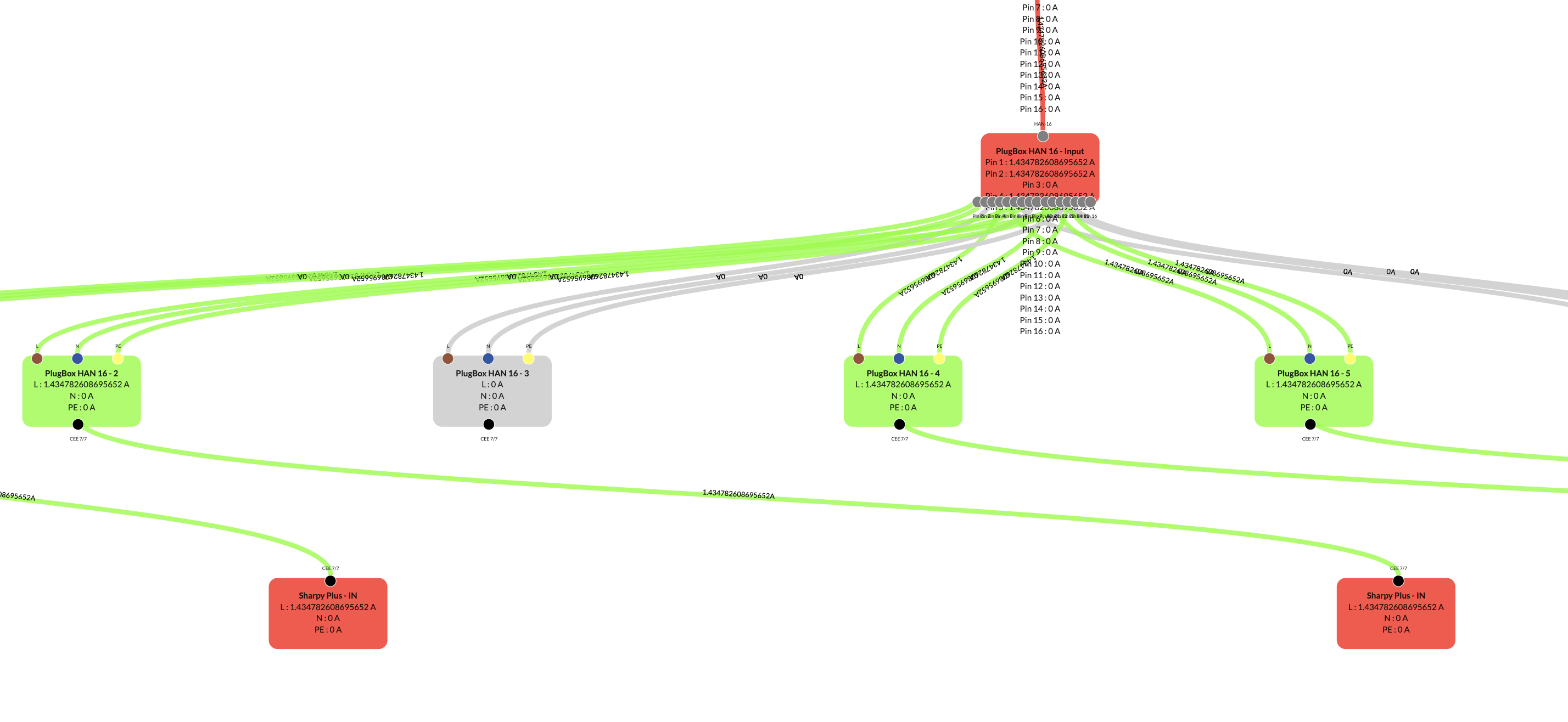
You can either move around in the window with the mouse or use the zoom buttons at the bottom left.
In the menu bar under Window Worksheets under Electrical Overview you will find an overview of your electricity consumers and their consumption.
The All Loads tab shows you all consumers in the system with their number, power consumption and position (Assembly Group) and power source. In addition, you will find an overview of all power sources in the system with their position (Assembly Group) and their availability period.
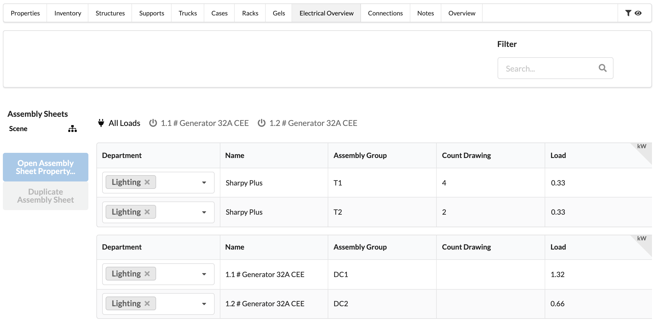
In the registers of the individual power sources, you also have an overview of which power consumers are connected to this power source, what consumption they have and at which position ( assembly group ) they are located.
In this list you can only edit the department of the objects and the provision time of the power connection. Everything else is for viewing only.
The Electrical Connection List shows the electrical connections of the individual objects. Cable lengths can also be defined here later.
The electrical network just described can be displayed in the menu bar (menubar) under the menu item “Window” by clicking on option “Electrical Network” .
In this list, you can only edit the Department of objects. Everything else is for viewing only.
You can sort the content by that column by clicking on the column header, and you can adjust the width of the columns by clicking and dragging the dividers. You can change the order of the columns by dragging and dropping.