

Symbols and fixtures provide reusable objects for your drawing. A symbol definition can contain geometry and other elements. You can edit the definition in Edit Mode, map MVR symbols using a Symbol Map, and choose the appropriate resource source when inserting an object. The available Resource Manager actions are described in Resource Manager.
Symbol definitions are reusable resources that can contain geometry and other elements, such as electrical connections, inventory data, or structural data.
A fixture uses a Fixture Type with device data such as modes, DMX channels, and gobos. Fixture Types are usually imported from a GDTF file.
GDTF stands for “General Device Type Format”. It describes a device, including its geometry and control data. Import a .gdtf file using File → Import → Import GDTF... or in the Resource Manager under Fixture Types. The import creates a Fixture Type in the current drawing; it does not place a fixture. To place one, select New Object → GDTF in the Toolbar, then choose the imported type from Current Drawing. For more steps, see the GDTF and MVR Workflow.
Use a Symbol Map to assign a matching Production Assist symbol to an incoming symbol name. When importing an MVR file, you can review and apply the proposed mapping. Saved mappings are offered again for later MVR imports; they do not retroactively change objects that have already been imported. You can manage mappings in the Resource Manager under Symbol Map. For the full steps to add, edit, copy, and delete mappings, see Symbol Map in the Resource Manager.
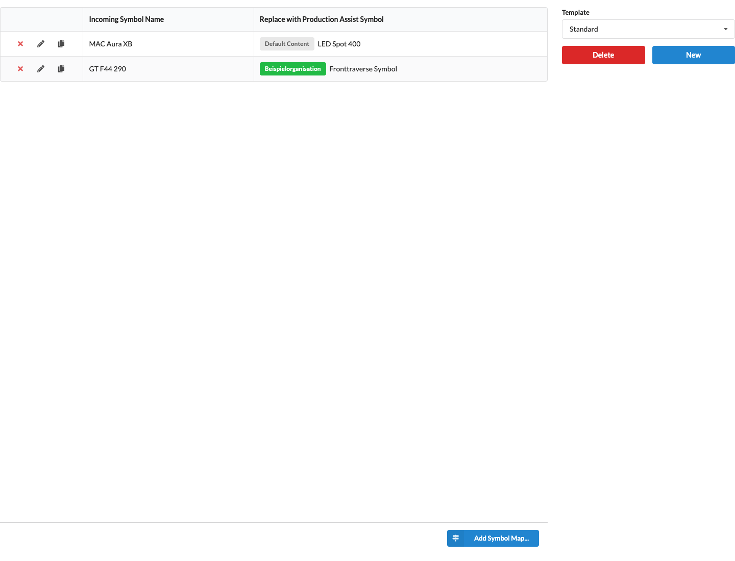
The Resource Manager shows existing mappings between incoming symbol names and Production Assist symbols. For MVR files, the mapping is also shown in the Symbol Map import dialog.
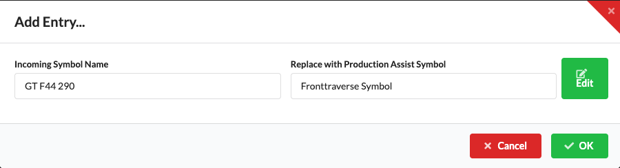
Use the step-by-step guide Creating or deleting a symbol mapping to specify the incoming and replacement symbols. The mapping does not replace existing objects retroactively.
Templates help you keep different symbol mappings ready for different MVR sources. The available template actions depend on whether the drawing is linked to an online project. They are described in the Templates section of Symbol Map.
The resource selector offers four sources. Available content depends on the resource type and your access:
Current Drawing shows resources that are already in the active drawing.
Local Resources shows .lrwx drawings stored on this computer, which are also available without an internet connection. Click Open Local Resources Folder to open the corresponding folder in the file system. You can place your own .lrwx files in this folder. Use this command instead of entering a fixed storage path because the actual folder depends on the system.
Online Drawing shows resources from an online drawing and the online library. You need an internet connection for online content; project-specific content also requires the necessary project access.
User Resources shows resources from a selected user account. Select the desired account in the tab. Availability and editing rights depend on the resource and project access permissions.
The libraries for CAD host applications use their native file formats: AutoCAD and BricsCAD provide blocks as individual DWG files; SketchUp uses components from the ProductionAssistLibrary folder as SKP files. The BricsCAD installation includes the DWG library in the plug-in folder. In SketchUp, add the extracted library folder as a local collection. Open the AutoCAD library through the DWG Browser; it requires a configured library path.
Use the prepared libraries so that geometry and Production Assist properties are available together. Which properties a custom or third-party file contains depends on how it was created or exported; check structural, support, inventory, and electrical data in particular before calculating. Details are available in AutoCAD: Browse the DWG Library, BricsCAD: Add the Production Assist Library, and SketchUp: Use the Component Library.
To make a symbol definition available for future projects or other team members, upload it to an authorized user or organization account. Uploading and the required access rights are described in Share content with other team members. Uploading a resource to your user account does not automatically make it available to everyone.
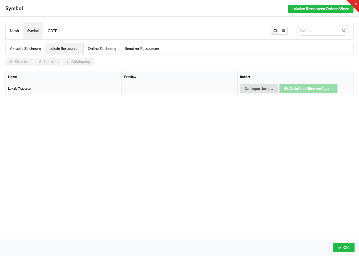
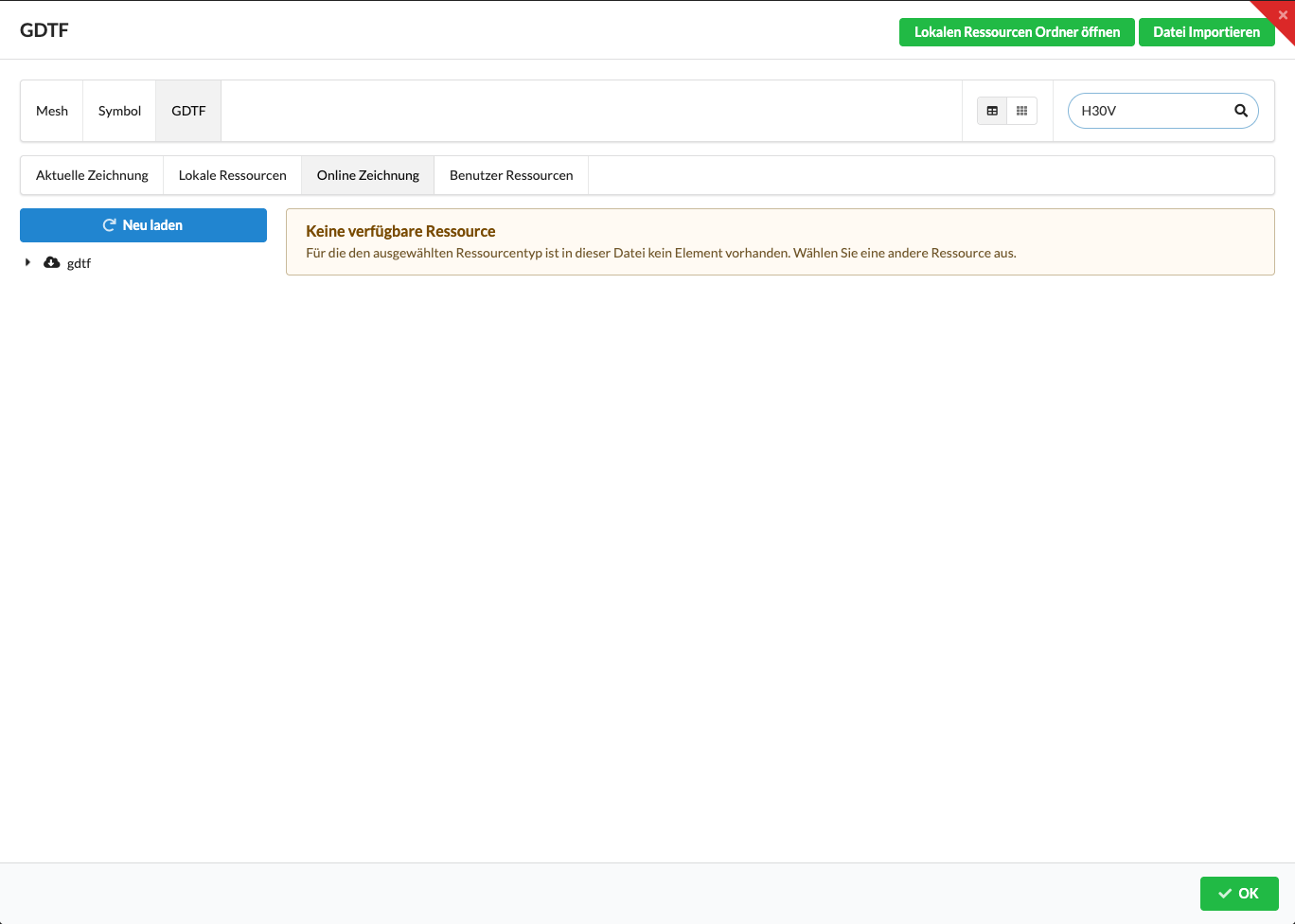
In Online Drawing and User Resources, you can browse the folder structure and search by name. Depending on the source and resource type, the selector shows Import... or Download & Import. If Production Assist needs to download an online resource first, you need an internet connection. For the next steps to insert resources, see the MVR Quick Start.
Open the definition of a symbol in use if you want to change its geometry or the elements stored in it. You can open Edit Mode in three ways:
The Renderer switches to Edit Mode. The Scene Tree now shows the elements of the definition. Select an element to edit or delete it. To rename an element, edit its name in the Scene Tree. The available object and geometry properties depend on the selected element.
Use New Object in the Toolbar to add more elements. The Edit Mode insertion options are listed in Symbol Elements.
To finish, select Close and Save or Close without Saving in the Renderer. Saved changes to a symbol definition apply to all drawing objects that use that definition.
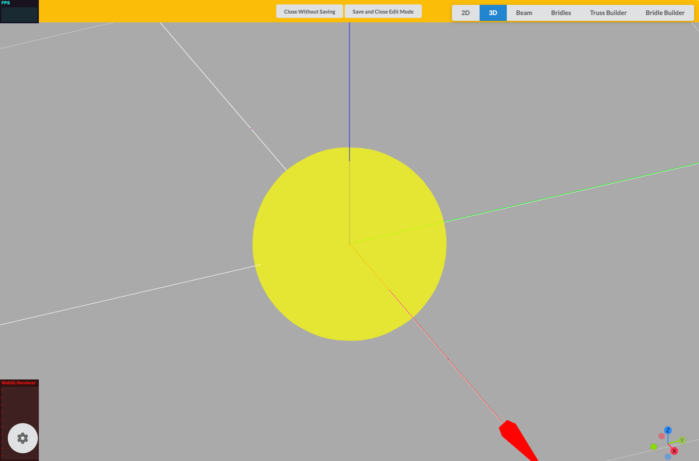
Use New Object in Edit Mode to insert 13 element types into a symbol definition. These include groups, geometry, and technical data. The entries below describe the buttons; for translated buttons, the internal element name appears in parentheses.

Adds a group as a container for child elements.
Adds the symbol's 3D geometry.
Defines snap points that can align compatible objects when placing or connecting them, for example at the ends of trusses.
Adds electrical connections. Set their connection type and connector type in the properties.
Adds accessory data that can appear in the object properties and in relevant inventory lists.
Adds structural and cross-section data for structural objects.
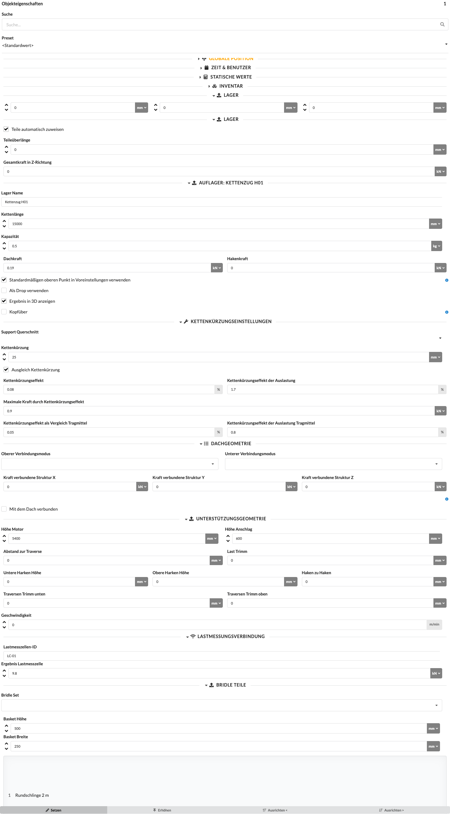
Adds support or suspension data, such as chain length and load capacity.
Marks the position of an audio source in the symbol.
Adds a reference point in the symbol definition. You can select it in Object Properties as the origin reference for suitable positioning and suspension functions.
Adds curtain geometry.
Adds a two-dimensional path. Depending on its settings, it can be closed, filled, or extruded.
Defines a point or line load within the symbol. Load components, length, and load group determine how the load is included in the structural calculation.
Defines a cable dock point. In the object properties, you can assign cable connections to it and specify whether cables are disconnected there.
A Mesh element adds 3D geometry to a symbol. For information about available mesh resources and how to manage them, see Meshes in the Resource Manager.
Use Magnet elements to define snap points that align compatible objects when placing or connecting them. For truss symbols, magnets are usually placed at both ends of the symbol definition.
The renderer image in the Edit Mode section also shows the magnet geometry at the endpoints.
Use an Electrical element to add an electrical connection (Wire) to the symbol definition. Select the connection and, in Object Properties, set its Type and, if available for that type, its Connector. Production Assist shows additional properties depending on the role.
The rendered example shows an electrical Input with the CEE 16A connector and example assignments for L1 and N. A distributor can contain additional inputs and outputs. You can name each connection using Name in Object Properties.
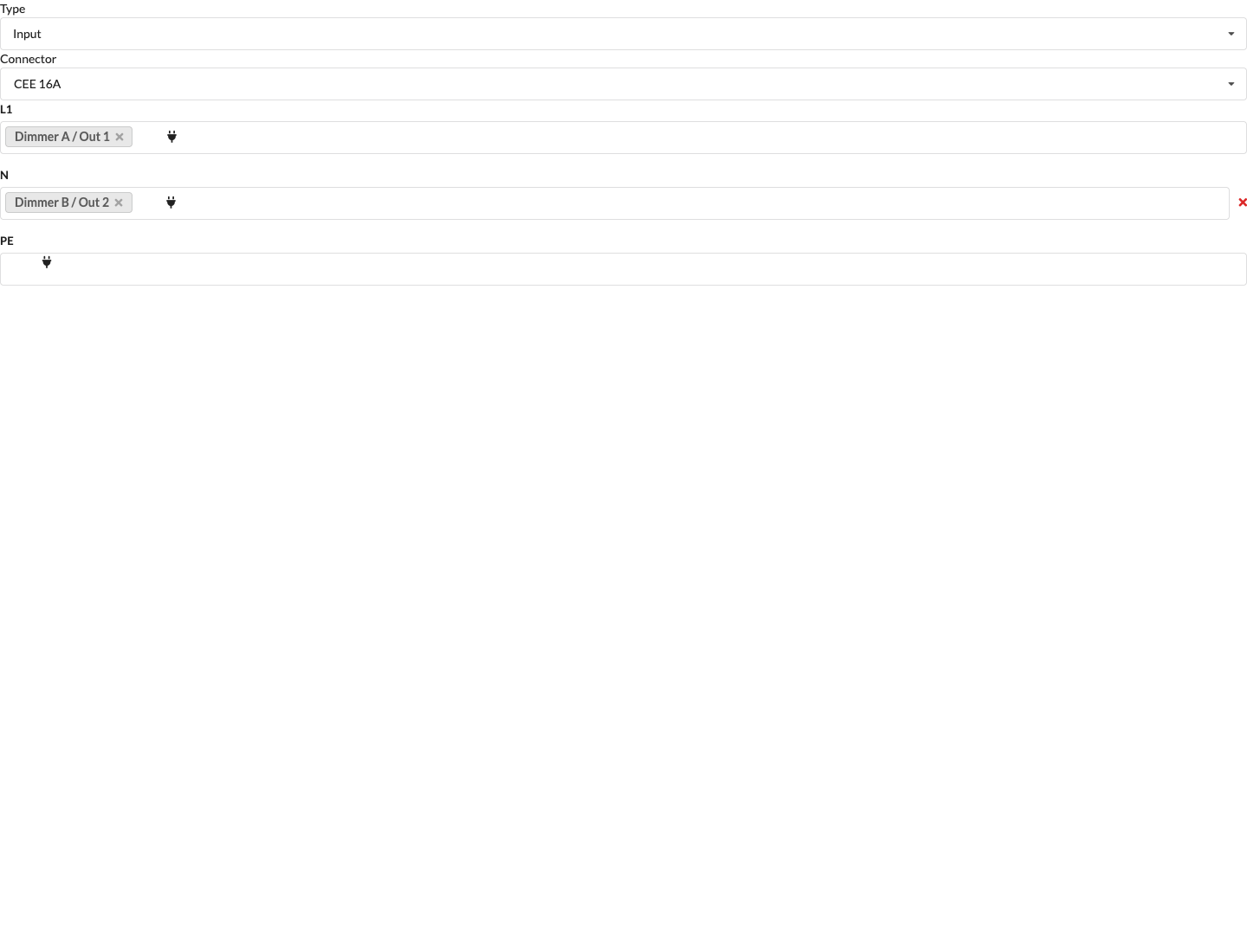
The connector determines which connection pins and conductors are offered for assignment.
The available connector types depend on the connector types in the drawing. Depending on the project, options may include Schuko, CEE, and Harting connectors.
For Input and Output, assign the pins to the appropriate conductors in the Electric section, for example L1, N, and PE. The available pins depend on the selected connector.
Type defines the role of the connection. The options are Input, Output, Generator, Consumer, and Fuse. An object can contain connections with different roles, such as a distributor with inputs and outputs. For Consumer connections, set Consumer is dimmable and the electrical power, among other properties, in Object Properties. The Power Planning Workflow describes how to assign consumers, distributors, and power sources. Pin assignments apply to the supported connection roles; they are not shown for every type.
Use an Inventory element to add an accessory to an object so that it can be included in inventory lists. Select the element in Edit Mode to name it in Object Properties and set its Count and other inventory values. In the example, the element is named “Pins Truss H30V-500” and its count is 4. The count is an inventory property of the element, not part of Time & User.
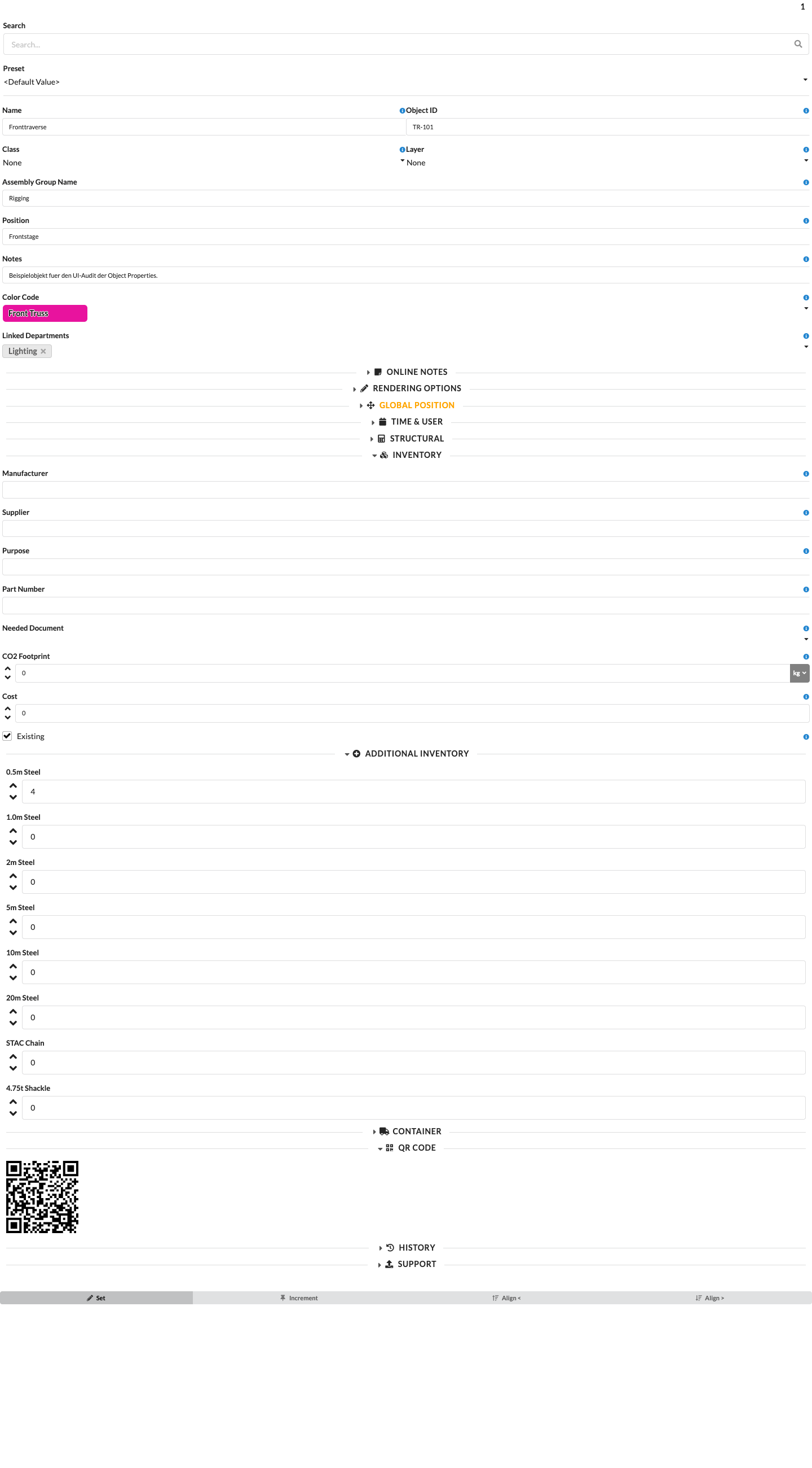
The Inventory Items stored in the symbol appear under Additional Inventory in Object Properties for objects that use it. You can adjust the count for the object there. To include the accessory in the Worksheet inventory list, enable Show Accessories in the inventory options there.
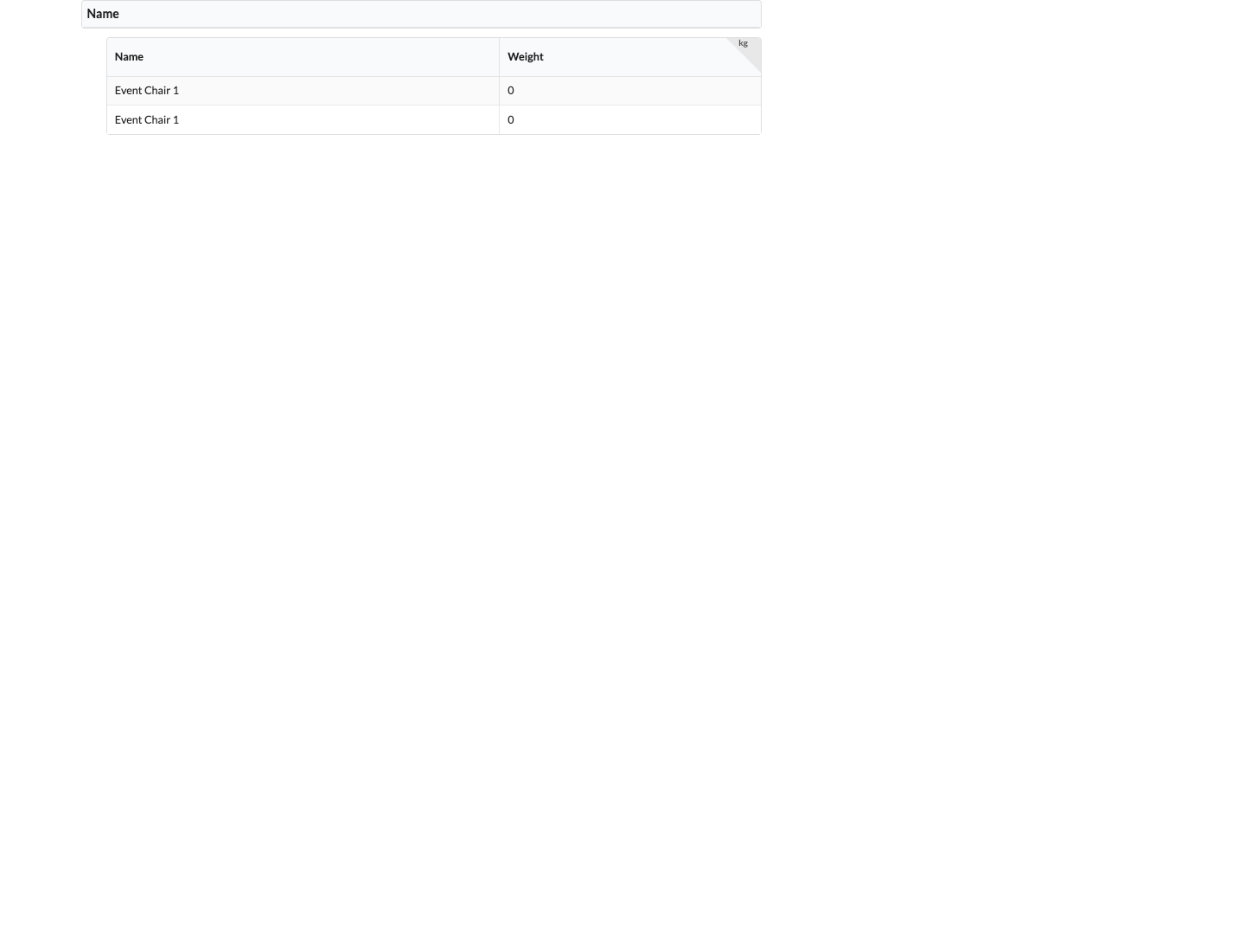
For inventory geometries in a Bridle material set, the Edit material set… editor is also available in the Bridle View. There you can add or remove local rope, shackle, and chain parts, name them, assign color codes, and edit their dimensions and component values. Save material set updates the existing bridles in this set in the current drawing together with the resource; manual slings retain only the parts that are still available to them. Other geometry types remain unchanged.
Adding structural geometry to a symbol lets you assign structural data such as cross-section data. This is required for structural calculations.
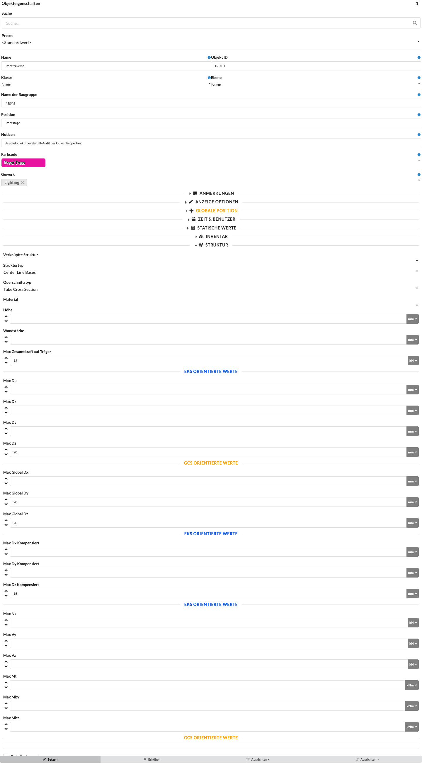
A truss symbol that will be connected to other objects needs Structure elements for its structural endpoints and Magnet elements for alignment during snapping.
The yellow structural geometry and the snap points at its endpoints are also visible in the renderer image in the Edit Mode section.
Adding Support geometries to a symbol definition lets you define the start and end points for supporting a load on a new object, for example for chain hoists or supports.
Support elements define the suspension or support points of the symbol definition. Select a Support element and, in Object Properties under Support, set the Chain Length and Load Capacity. In the example, the two support points are at the ends of the truss.
An Audio element marks the symbol as an audio object and indicates the position of an audio source.
An Origin element provides a reference point within the symbol. Other functions can use this point as the origin reference, for example when selecting an origin in Object Properties. A symbol definition without a suitable reference is not offered there.
A Curtain element adds curtain geometry to the symbol.
A Polygon element defines a contour. Select the element and, in Object Properties, set Closed, Fill, and, if needed, the Extrusion Height. This lets you display an open line, a filled area, or a three-dimensional shape.
A Load element defines an additional load in the symbol. Set its force components, its length for a line load, and the associated load group. The geometry and direction determine where and how the load is applied. The Load Groups section explains load groups and their factors.