

Whether a structure is statically determinate or indeterminate describes whether its support reactions can be determined from the equilibrium conditions alone. This depends not only on the number of suspension points, but also on which movements the supports prevent, how the system is connected, and whether it is stable.
A structure with insufficient support or pinned connections may be a moving mechanism. It is then not simply a statically determinate system: it has no stable equilibrium position. The examples on this page show idealized beam models; real trusses, rigging, and connections can behave differently.
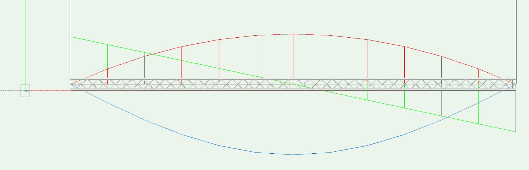
Example deflection (blue), bending moment (red), and transverse force (green) for a statically determinate system.
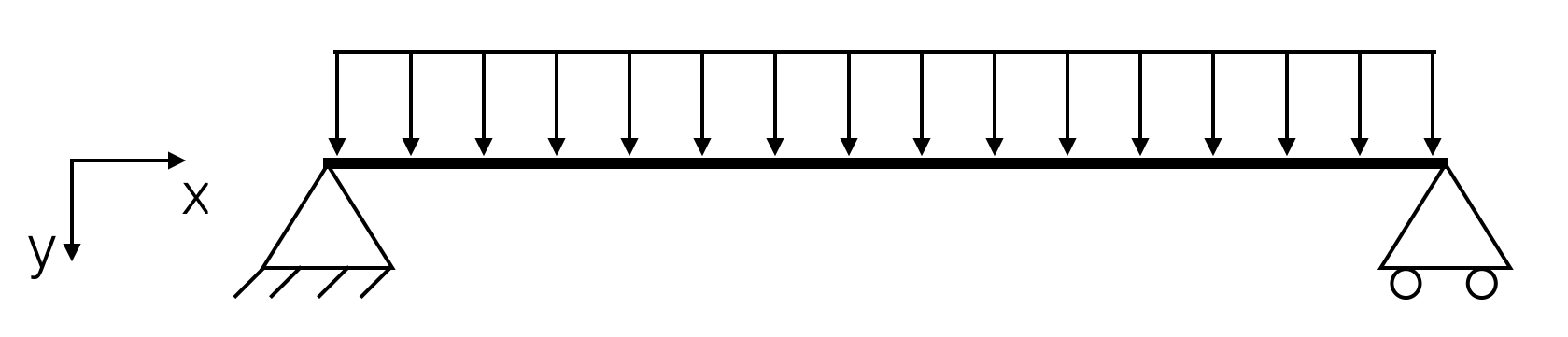
Idealized beam with a uniformly distributed load, one fixed support, and one roller support.
For the plane beam shown, the two vertical support reactions can be determined from moment and force equilibrium. In the formula, q is the uniformly distributed load per unit length, l is the span, and F_A and F_B are the vertical support reactions.
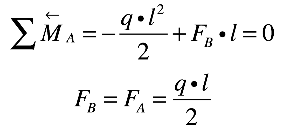
Equilibrium equations for the illustrated special case of a uniformly distributed load.
The example applies to the geometry, supports, and load distribution shown. It is not a general rule that every structure with two or three suspension points is statically determinate. Classification requires checking the complete model, including the restrained directions of movement and the connections.
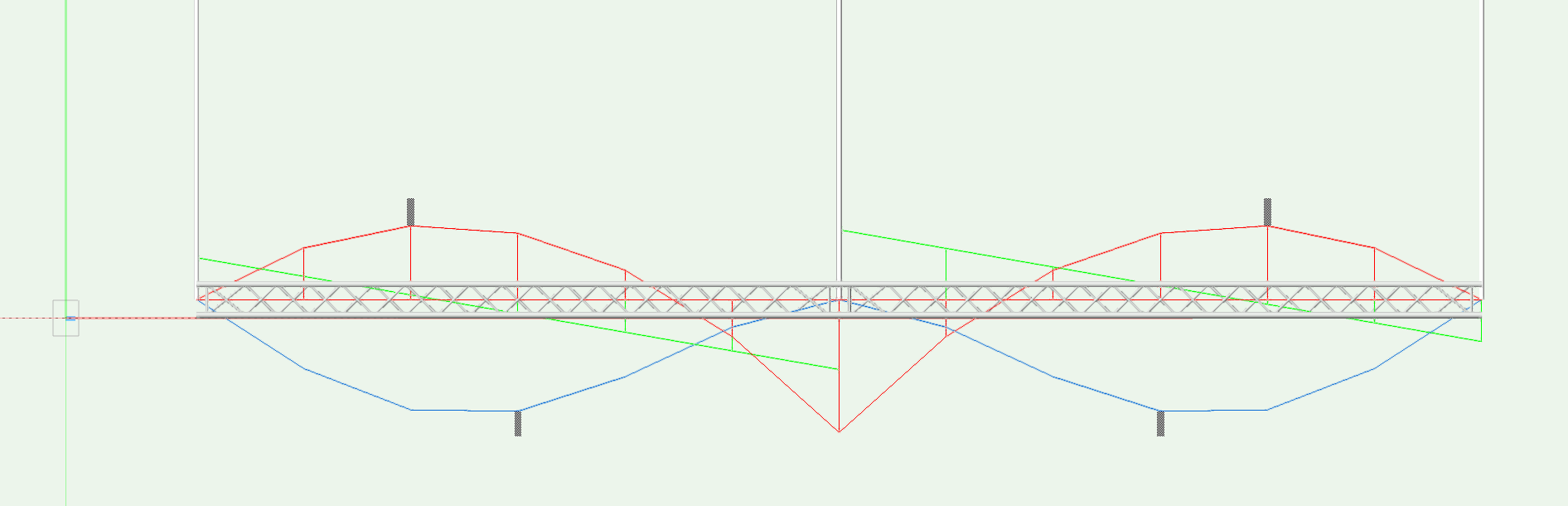
Example deflection (blue), bending moment (red), and transverse force (green) for a continuous beam.
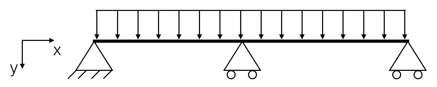
Idealized continuous beam with three supports.
For the plane system shown, there are more unknown support reactions than independent equilibrium conditions. Equilibrium alone therefore cannot determine the reactions uniquely. For a stable statically indeterminate system, the solution also depends on deformation compatibility and the system's stiffness. As a result, small changes in geometry or support position can change the support reactions.
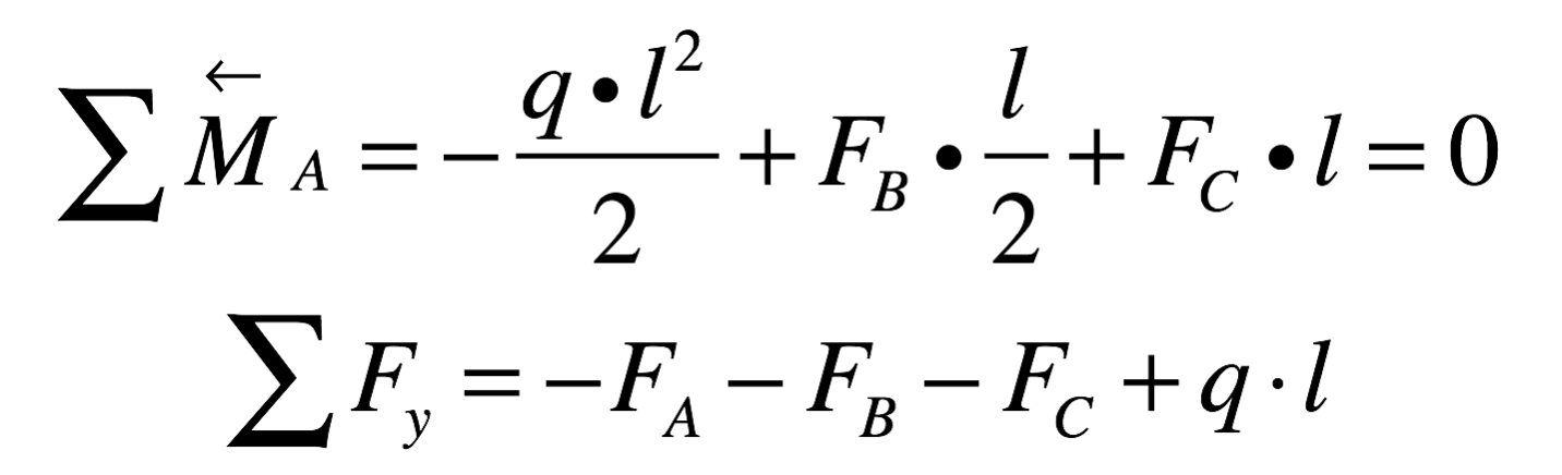
In the example shown, the equilibrium conditions alone are not sufficient to determine all support reactions.
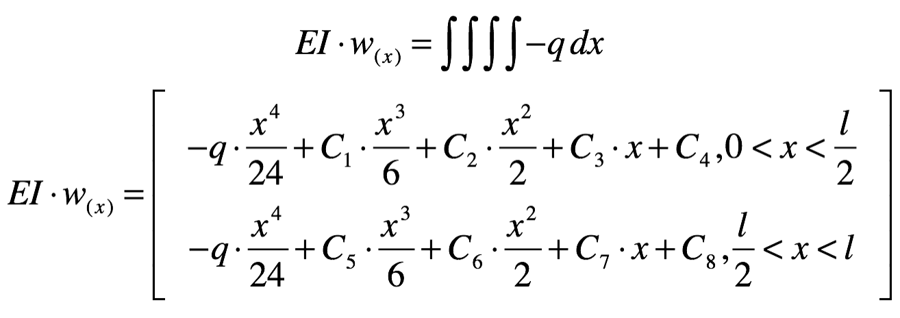
Illustration of an integration approach for the beam shown. E is the modulus of elasticity, I is the second moment of area, w(x) is the deflection, and q is the distributed load.
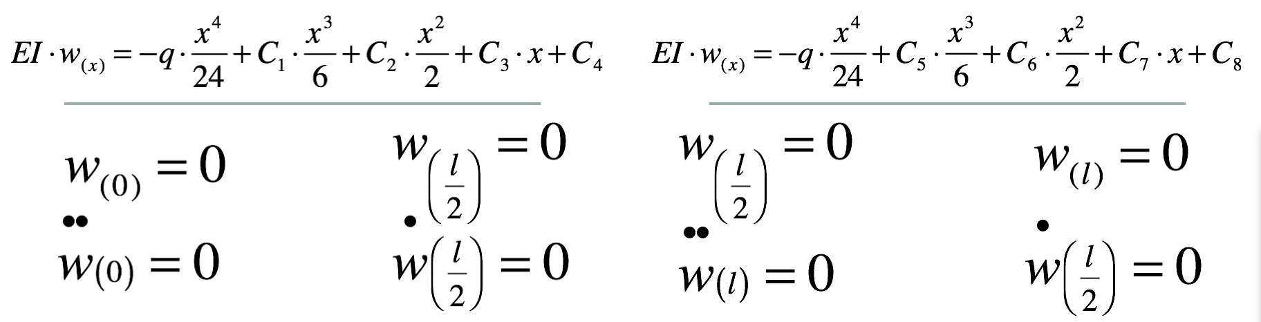
The integration constants are determined from boundary and transition conditions that match the supports and connections.
The formulas illustrate an idealized beam approach. Boundary conditions must match the actual calculation model. For example, deflection is zero at an ideal support; this does not mean that every possible movement or rotation is prevented at every support. In practice, Production Assist uses its stored structural model and its material and cross-section data. The figures are not a complete calculation procedure for arbitrary structures.
For statically indeterminate structures, small height deviations or deformations can affect load distribution. Rope shortening lets you examine the vertical displacement of a suspension point in the calculation. It is a simulation parameter in millimetres, not an instruction to physically shorten a rope.
Chain shortening deliberately changes the position of an individual hoist in the calculation. This lets you examine how adjusting a hoist affects load distribution. Results depend on the model, loads, supports, and selected displacements. In Production Assist, you can change chain shortening in the support properties, among other places, and examine its effect using the rigging commands. These calculations do not replace comparing the model with the planned structure or checking permissible forces and deformations.
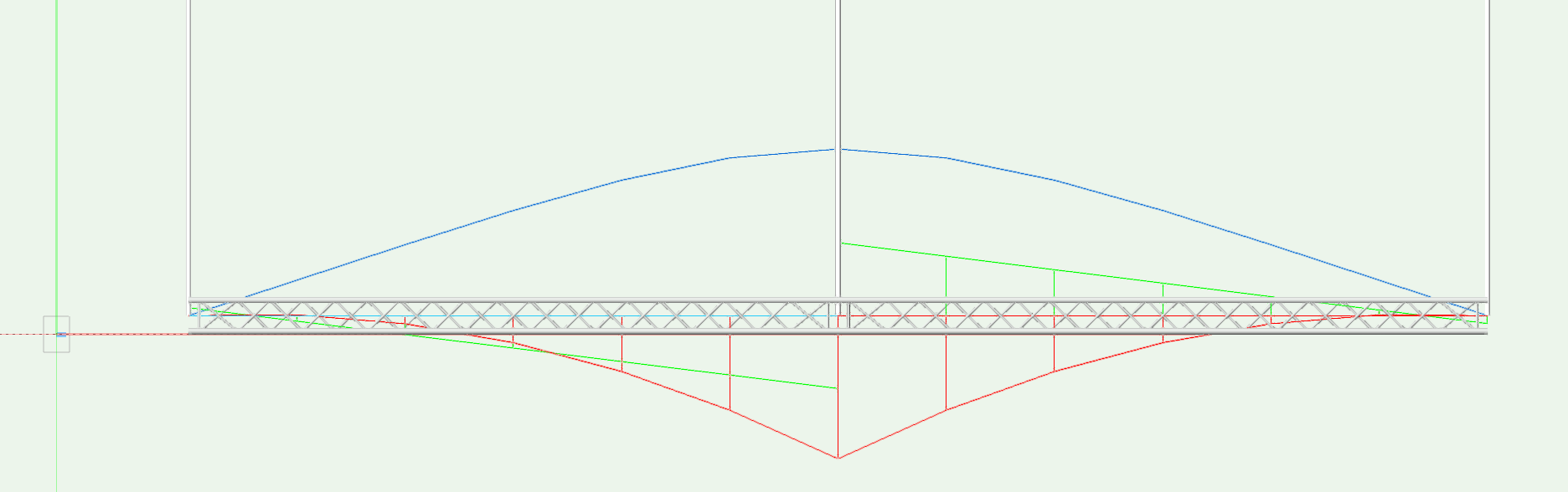
Example result change from a simulated rope shortening at the middle suspension point.
Compare calculated support positions and displacements with the approved construction documents. If the actual structure differs from them, or the results do not appear plausible, have the effects assessed by a qualified person. “Levelling” is not a universal requirement; follow the approved design and installation instructions.
Different travel speeds or motor start and stop operations can generate dynamic actions. A static calculation with adjusted rope or chain positions shows how a selected geometric deviation affects the static load distribution. It does not simulate motion over time, accelerations, or dynamic peak loads. To classify actions and load combinations, consider the actual situation and applicable requirements.